Original Build Log: https://mazdaspeeds.org/index.php?t...-auto-with-navigation-unit.16174/#post-113334
It's been a long time since I had finished the project, I lost track of time and forgot to write this out, but anyway! A lot of this is going to be taken from my build diary as I honestly didn't take too many photos of the installation because I was just in the flow of making it work; but I'll be compiling everything I have for it. The main thing you'd need to do this yourself is getting familiar with what wires you're going to be messing with, and how these wireless android auto unit's work as it's something you can buy for any car and not specific.
This is meant for Gen1 Mazda3's, or Gen1 Mazdaspeed3's that don't have the GPS Navigation Unit installed already. In my case, I drive a 2007 Mazdaspeed3 Sport without the Nav unit.
ITEMS USED:


(images included in-case links die)
Quick notes about the items used:
THE ANDROID AUTO/CARPLAY MODIFICATION:
In essence what you're doing is using the factory screen board still drive the motor that opens/closes the screen. While the Android Auto/Carplay is a separate unit that's powered by a cigarette charger. There is another way to do this with an Arduino but I did not go that route, however it will be linked at the bottom for someone else to figure out. If you have this unit in your hands and want to do this yourself, I urge you to take it apart to get familiar with how the mechanism works for wire clearance (will be important later).
Gut all electronics and test fit your screen:

Check screen bezel's:

Install the screen by breaking off clips from the original metal screen retainer and screw it into the posts:

Notice the broken ground on the left, you don't necessarily need this anymore since it isn't really drawing much current with the screen removed, there is already a ground in the ribbon cable. This is how it should sit. By this photo you should also notice that the main board for the screen is removed from the housing:

I had to trim off a part of the IR sensor cover for the screen to sit flush:

What I've done to clearance the wires is cut an extra slot next to the ribbon cable location for the USB cable.

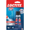
Super gluing the wires together, it will also stick to the plastic housing to keep it all together and not run into the ribbon cable. You will find that if you don't it will run into the ribbon cable each time you open/close the screen. You don't want that otherwise it'll wear out sooner. You may be able to make this better by instead making a separate hole, or gluing a pillar between them:

Here is how the screen sits right now inside my car, yes the USB C Adapter could've been more elegantly placed but I wanted it to stay inside this unit so I don't have to be thinking about it down the line. I also placed foam tape and extra masking table around the ribbon cable so that the cables doesn't rub:

This concludes the Android Auto/Carplay Unit installation, you may run in an issue when you close the top of the screen and the power button gets depressed. You can shimmy the screen down some and then screw it down some. Or shave down the button. I chose the former.
WIRING:
Now it comes down to wiring the original screen board to the car's harness. To remind you, the motor and button functions are separate from the Android Auto/Carplay part. So first the wiring to get the original screen to function with your car's harness.
This is the schematic for the factory screen:


(Notice the order of the letters, the pattern repeats across the pin, this image corresponds to the harness you see below from this perspective. Meaning a letter seen here is exactly where it would be on the image below)
Here is the all important wires that you need to connect to your harness, the image below will give you an idea of what pins circled correspond to the pinout above.
(most of the pins you're looking for are on the right side)
24 Pin Connector:

I wish I took a better picture or laid out the wiring better but here is the wires I currently have soldered in my car right now (course liquid electrical taped it):

Now that you have the pinout from the factory screen board, you splice the connections into your headunit connector. Make sure to extend the wires as needed since the screen sits higher than you think from the headunit.
Your headunit may differ from mine but that's what mine looks like. Here is the pinout off the headunit:

(Source: https://pinoutguide.com/Car-Stereo-Mazda/Mazda_3_2004-2005_pinout.shtml)
Now you just wire them corresponding to the pinout off the display!
24 Pin Connector:
ROUTING:
I don't have any more photos to share about how I routed the wires because I was in the flow of getting it all routed and didn't spend the time to take a picture. So here's my best at describing what I did:
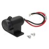
You use the Female Cigarette Socket to wire out of the Cigarette charger in parallel on the front center console (The orange one) so you can keep it clean and hide the power for the head unit.
The microphone is routed through the inside of the passenger dash (there are existing wires that you follow) up to the passenger A-Pillar, then reaching the dome light. You drill a hole at the top to fit the microphone sticking out, or make a small one.
I drilled out a hole for the USB-C socket to fit in. You route both the AUX and the USB through the transmission tunnel. There is a hole already there that comes from the cigarette charger area to the tunnel. Then make sure to push the wires down the sides, into the carpet so it won't interfere with your shifter.

Now you may notice I have a funny little button on the AUX!
I installed an AUX switch so that I can retain the normal AUX feature. Wired something like this:


I didn't save any notes for the pinout of the OEM Aux board nor the switching board, but honestly you can probably figure it out if you have a multimeter. If anything I think you should have one if you're planning to do this whole thing yourself. If want to figure out the pinouts, just know that it seriously is just 3 pins that mean anything from the AUX board, there are multiple that are redundant. I had cut some plastic off the housing and glued the button in position where it's seen in the picture of the center console. Otherwise if you don't want this, you can just wire your AUX lead coming from the Android Auto/Carplay device to the AUX board and you're done.
And that completes it! Hopefully someone finds some use in this information, because I sure as hell wish I had it when I did mine!

(Custom Boot Logo)

(Button Illumination)

(Completed)
Bonus Arduino Method:
There is a whole other way to make the pop-up screen work by using an arduino board to control the motor and read from the buttons. The RX8 and the Mazda6 had similar screens which in this case, the arduino code is for a Mazda6. There is another one written for the RX8, however I never figured out how both of them work when it comes to the pins and I just found it easier to just re-use the original screen board.
Anyway, here are the related links:
RX8:
https://www.rx8club.com/series-i-interior-audio-electronics-24/my-car-tablet-237158/
https://github.com/dasonwong/rx8navhood/blob/master/RX_8_NavHood_Control.ino
Mazda6:
https://github.com/amd989/Navi/tree/master
It's been a long time since I had finished the project, I lost track of time and forgot to write this out, but anyway! A lot of this is going to be taken from my build diary as I honestly didn't take too many photos of the installation because I was just in the flow of making it work; but I'll be compiling everything I have for it. The main thing you'd need to do this yourself is getting familiar with what wires you're going to be messing with, and how these wireless android auto unit's work as it's something you can buy for any car and not specific.
This is meant for Gen1 Mazda3's, or Gen1 Mazdaspeed3's that don't have the GPS Navigation Unit installed already. In my case, I drive a 2007 Mazdaspeed3 Sport without the Nav unit.
ITEMS USED:
- Gen1 Mazda3 GPS Navigation Unit (Thanks Raider)


- AUX w/Angled Connector (ideally you want a long one)


- Original Loctite Super Glue (Sometimes seen as Liquid Loctite)

- USB Extender Angled (Optional)

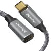
- USB C 2.0 Male to Female Square Flush Mount (Optional)

- USB Type-A to Type-C Adapter (Optional)

- AUX Switching Board (Optional)

- Dupont Line (Optional, Use line you like)

(images included in-case links die)
Quick notes about the items used:
- You can use any Android Auto/Carplay Unit so long as it's 7 inches and that it will fit into the screen cavity of the GPS Unit. Usually the 7inches means the entire glass portion so it shouldn't be an issue with which one you pick. (Use amazon for easy returns on this)
- The Optional items are for if you want a USB input to the Android Auto/Carplay unit. You do not need this BUT it is the only way to communicate physically to the device if you ever need to update the unit. For the Carpuride C3, it functions as data to the unit for your phone instead of JUST wireless, as well as charging. It can take bios flashes through that same USB port. (It'd be a good idea to have just in-case and also you can customize your boot logo)
- I wired the USB in a weird way because I wanted it to be a USB C port rather than the normal USB A, however you can do what you want.
- The Carpuride C3 has awful charging speeds, do not expect it to replace your normal cigarette charger if you have one. However I really like this unit for it's touch response speed. I've went through 2 other ones that I returned that ran like a powerpoint slideshow from the Vista era.
THE ANDROID AUTO/CARPLAY MODIFICATION:
In essence what you're doing is using the factory screen board still drive the motor that opens/closes the screen. While the Android Auto/Carplay is a separate unit that's powered by a cigarette charger. There is another way to do this with an Arduino but I did not go that route, however it will be linked at the bottom for someone else to figure out. If you have this unit in your hands and want to do this yourself, I urge you to take it apart to get familiar with how the mechanism works for wire clearance (will be important later).
Gut all electronics and test fit your screen:
Check screen bezel's:
Install the screen by breaking off clips from the original metal screen retainer and screw it into the posts:
Notice the broken ground on the left, you don't necessarily need this anymore since it isn't really drawing much current with the screen removed, there is already a ground in the ribbon cable. This is how it should sit. By this photo you should also notice that the main board for the screen is removed from the housing:
I had to trim off a part of the IR sensor cover for the screen to sit flush:
What I've done to clearance the wires is cut an extra slot next to the ribbon cable location for the USB cable.
Super gluing the wires together, it will also stick to the plastic housing to keep it all together and not run into the ribbon cable. You will find that if you don't it will run into the ribbon cable each time you open/close the screen. You don't want that otherwise it'll wear out sooner. You may be able to make this better by instead making a separate hole, or gluing a pillar between them:
Here is how the screen sits right now inside my car, yes the USB C Adapter could've been more elegantly placed but I wanted it to stay inside this unit so I don't have to be thinking about it down the line. I also placed foam tape and extra masking table around the ribbon cable so that the cables doesn't rub:
This concludes the Android Auto/Carplay Unit installation, you may run in an issue when you close the top of the screen and the power button gets depressed. You can shimmy the screen down some and then screw it down some. Or shave down the button. I chose the former.
WIRING:
Now it comes down to wiring the original screen board to the car's harness. To remind you, the motor and button functions are separate from the Android Auto/Carplay part. So first the wiring to get the original screen to function with your car's harness.
This is the schematic for the factory screen:

(Notice the order of the letters, the pattern repeats across the pin, this image corresponds to the harness you see below from this perspective. Meaning a letter seen here is exactly where it would be on the image below)
Here is the all important wires that you need to connect to your harness, the image below will give you an idea of what pins circled correspond to the pinout above.
(most of the pins you're looking for are on the right side)
24 Pin Connector:
- Q (Battery Positive) = Orange
- O (Accessory) = Yellow/Blue Silver Dots
- P (Ground) = Black/Orange
- V = (TNS Signal for Illumination Positive) = Orange Silver Dots (Optional for Button Illumination)
- X = (Illumination Ground) = Black/Orange Silver Dots (Optional for Button Illumination)
- A (Accessory) = Yellow/Blue Silver Dots
- (Other TNS is not required)

I wish I took a better picture or laid out the wiring better but here is the wires I currently have soldered in my car right now (course liquid electrical taped it):
Now that you have the pinout from the factory screen board, you splice the connections into your headunit connector. Make sure to extend the wires as needed since the screen sits higher than you think from the headunit.
Your headunit may differ from mine but that's what mine looks like. Here is the pinout off the headunit:

(Source: https://pinoutguide.com/Car-Stereo-Mazda/Mazda_3_2004-2005_pinout.shtml)
Now you just wire them corresponding to the pinout off the display!
24 Pin Connector:
- (Battery Positive) = Orange : Orange/Black
- (Accessory) = Yellow/Blue Silver Dots : Yellow
- (Ground) = Black/Orange : Black/Green
- (TNS Signal for Illumination Positive) = Orange Silver Dots : Orange/Black Silver Dots
- (Illumination Ground) = Black/Orange Silver Dots : Black/Green Silver Dots
- A (Accessory) = Yellow/Blue Silver Dots : Yellow
- (Other TNS is not required)
ROUTING:
I don't have any more photos to share about how I routed the wires because I was in the flow of getting it all routed and didn't spend the time to take a picture. So here's my best at describing what I did:
You use the Female Cigarette Socket to wire out of the Cigarette charger in parallel on the front center console (The orange one) so you can keep it clean and hide the power for the head unit.
The microphone is routed through the inside of the passenger dash (there are existing wires that you follow) up to the passenger A-Pillar, then reaching the dome light. You drill a hole at the top to fit the microphone sticking out, or make a small one.
I drilled out a hole for the USB-C socket to fit in. You route both the AUX and the USB through the transmission tunnel. There is a hole already there that comes from the cigarette charger area to the tunnel. Then make sure to push the wires down the sides, into the carpet so it won't interfere with your shifter.
Now you may notice I have a funny little button on the AUX!
I installed an AUX switch so that I can retain the normal AUX feature. Wired something like this:
I didn't save any notes for the pinout of the OEM Aux board nor the switching board, but honestly you can probably figure it out if you have a multimeter. If anything I think you should have one if you're planning to do this whole thing yourself. If want to figure out the pinouts, just know that it seriously is just 3 pins that mean anything from the AUX board, there are multiple that are redundant. I had cut some plastic off the housing and glued the button in position where it's seen in the picture of the center console. Otherwise if you don't want this, you can just wire your AUX lead coming from the Android Auto/Carplay device to the AUX board and you're done.
And that completes it! Hopefully someone finds some use in this information, because I sure as hell wish I had it when I did mine!
(Custom Boot Logo)
(Button Illumination)
(Completed)
Bonus Arduino Method:
There is a whole other way to make the pop-up screen work by using an arduino board to control the motor and read from the buttons. The RX8 and the Mazda6 had similar screens which in this case, the arduino code is for a Mazda6. There is another one written for the RX8, however I never figured out how both of them work when it comes to the pins and I just found it easier to just re-use the original screen board.
Anyway, here are the related links:
RX8:
https://www.rx8club.com/series-i-interior-audio-electronics-24/my-car-tablet-237158/
https://github.com/dasonwong/rx8navhood/blob/master/RX_8_NavHood_Control.ino
Mazda6:
https://github.com/amd989/Navi/tree/master
Attachments
Last edited:


