HOW-TO MAZDASPEED3 REPLACE CLUTCH
This was done on a genpu, the gen1 requires the exactly the same procedures. This is meant to be a helpful walk through for doing a clutch swap on a MS3. This job should be performed ONLY BY PROFFECIONAL EXPERIENCED TECHNICIANS. I’m not liable for any mistakes you make, following this guide, which is probably not 100% accurate. This is probably a 12hr job according to Mazda, but it can be accomplished in <5hrs if you know what you’re doing.
Tools Required:
Socket Wrenches
Socket Sizes Used Most:
10mm
12mm
14mm
17mm
19mm
21mm
24mm
Ratcheting Wrenches(not necessary, but helpful):
10mm
12mm
14mm
17mm
Torque Wrenches
A Decent Screwdriver Set
Pry-Bars
Very Tall Jack Stands or a Lift
Transmission or Motorcycle Jack
Good Set of Pliers
Various Pieces of Wood
Hammers
Other Miscellaneous Hardware:
Brake-Clean
Grease
Thread-Lock
New Flywheel Bolts
New Trans Fluid
Rags, Towels, etc.
Coat Hangers, Rope, Wire, etc.
Drain Pan
Die-Grinder
Air Tools, Impact Guns
Piece of cardboard, and marker(to keep track of bolts)
Recommended to Replace:
Flywheel Bolts
Driveshaft Seals
Driveshaft C-Clip(only 1)
First, start by jacking the car in the air, or using a lift if you have one.


Begin by removing the undertray, front wheels, intake, battery, battery box, ECU, basically everything above the transmission.
Remove the brackets for the wiring harness and shift cables on the top of the trans, there is 3 brackets show here, all are being held on by 2 bolts IIRC:

Unbolt the coolant hard pipe running above the trans, as to access the trans bolts later, it’s held on by one 10mm nut on the front of the engine above the starter, and one 10mm bolt above the bellhousing towards the back of the engine:

Unclip the electrical connectors from the trans, located on a bracket on the front of the engine:


Remove the slave cylinder, from the bellhousing, two 12mm bolts, no need to remove the slave from the fluid line:

Next, drain all the trans fluid. Crack the fill plug first, just to make sure it will come out later. The fill plug is located on the front of the trans and, drain plug is located on the side of the trans, shown here
Fill:

Drain:

Now begin tearing into the brakes and suspension. Remove the front calipers, held on by two 17mm bolts, and remove the rotors. Hang the calipers by the springs with some rope/wire.
Now remove the tie-rod safety pin then the 14mm nut:

Put the nut on the stud, and whack the nut till the tie rod is free from the knuckle:

Remove the upper sway-bar end-link nut, remove the end-link from the strut and put the nut on it, so you don’t lose it(14mm and some metric hex key size… I just zip these off with an impact, since they’re usually rusted to shit and don’t want to come off. If all else fails, cut the end-link off and buy new ones):

Remove the lower ball-joint bolt nut(14mm):

Remove the strut bolt(17mm):

It’s now time to free the strut from the knuckle. First take out a big hammer and pound on the knuckle shown here:

Do this until the knuckle moves down about 1cm. This will allow you now to pry the knuckle open and slide it off the strut. It needs to go down about 1cm, because the strut has a protruding piece of metal as to align it in the knuckle. Now you take some random piece of metal roughly ¼” thick and place it where the strut bolt goes. I’ve used this tiny wrench for my air grinder, as well as big washers, or pieces of metal I have laying around. Thread in the strut bolt the opposite way so it can press up against the piece of metal, effectively prying the knuckle open:


Take a pry bar and pry down on the knuckle to free it from the strut:

Thanks Daniel “silvapain” for this trick
Now it’s time to separate the lower ball joint from the knuckle. I’m sure with Mazda’s special tool, or a ball joint separator, it would be easier, but it can be done pretty simply with other methods. With the bolt out, the ball joint should come right out of the knuckle, but it being a very tight fit and some corrosion can lead to it being a bit difficult.
Support the hub with a jack-stand.

Then take a hammer and start pounding on the lower control arm, around where the ball joint is. Work at it till the ball joint is almost free. Use a pry bar, or lift up on the knuckle, to remove the knuckle.

Now that the hub/knuckle assembly is removed from the surrounding suspension components, it’s time to remove the axles.
We’ll start with the right axle, there is a joint shaft bracket that needs to be unbolted from the block, held in by 3 bolts.

Here’s a better pic of the joint shaft bracket, and it’s location:

Now the axle can be removed from the transmission. It helps to have a friend hold the axle level, while you can pry the axle out. The prying actions is as goes: use a pry bar, and with a jerking motion pry against the raised edge of the axle, in short bursts, to literally pop the axle out of the trans.

Once the axle/hub assembly is removed, from the trans, set it aside.
Do the same on the left side of the vehicle, and pop the axle out.
Some people say it’s not necessary to remove the subframe to pull the trans. It honestly does not need to be removed, I’ve done a clutch job before with the subframe in place. However, you will save yourself many hours of frustration, by removing it. Why? A portion of the subframe site right underneath the differential, and you’ll spend more time trying to wiggle the trans out of a very tight space. Plus the subframe takes 15min to remove.
Begin with the cross bar behind the subframe, IIRC this is where the bolts are located. The 14mm bolts shown in green, the 14mm nuts shown in yellow, and the one 10mm bolt that supports the fuel line shield portion of the cross bar in red:


Unhook the rubber exhaust hangers that connect the exhaust to the subframe, location in green:

Remove the heat shield on the powersteering rack(red arrow), three 10mm bolts. Then unbolt the powersteering rack from the subframe, three 19mm bolts(shown in green):

Here’s a pic of how to get the center bolt, from the rear of the car:

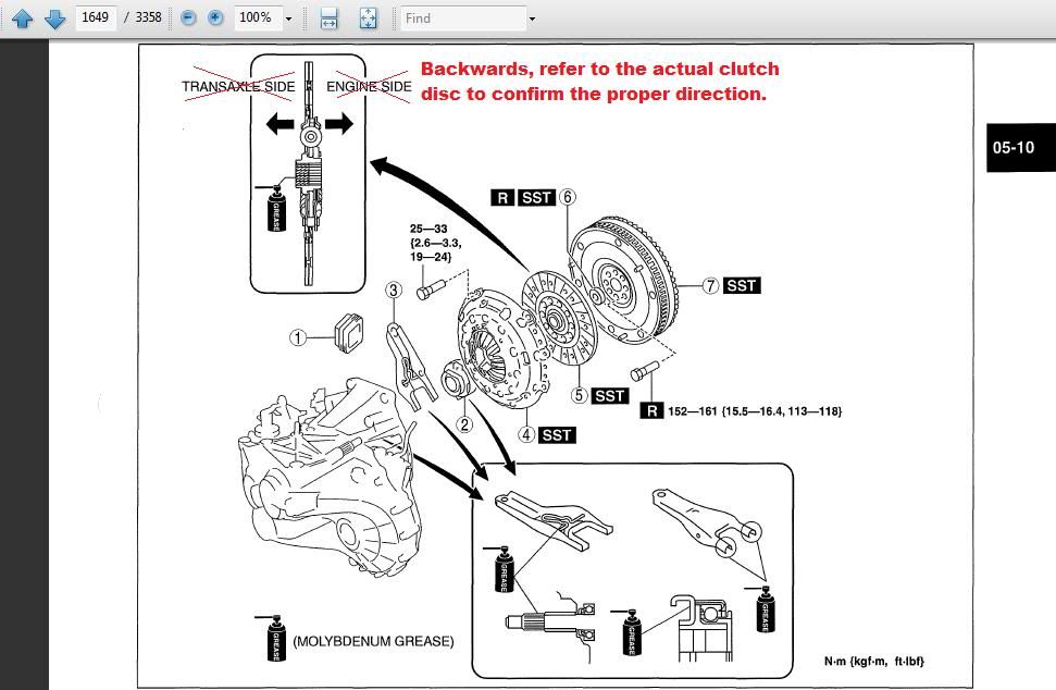
Here’s a pic from the shop manual:

Now with the rack unbolted, use bungee cords or zip ties, to secure the rack to the exhaust so it doesn’t fall with the subframe.
Unbolt the RMM from the trans:

Now it’s time to unbolt the subframe from the car. CAUTION! The subframe is heavy, support it on jacks/jackstands and have a friend on each side ready to pull it out, once unbolted from the vehicle.
There are 4 main bolts(front 19mm, rear 17mm), indicated in this pic:

Use extensions through the holes in the LCAs to get at the front two bolts:

Remove the 12mm bolts of the support brackets, shown in green, then remove the 17mm subframe bolt, shown in red. Do the same on the other side.

Now that the subframe is detached from the vehicle, lower it slowly, making sure everything is disconnected, and move it from underneath the vehicle. You’ll have to move the FSB/endlinks and tie-rods around so they don’t get caught up on each other.
Time to remove the trans mount. First support the engine as well as trans with whatever methods you have, leave room to remove the lover bellhousing bolts later, or skip a few steps, and pull out the lower bolts now:

This car had a CP-E trans mount at the time of this install. If you have a different aftermarket mount, refer to the supplier instructions, on how to remove it. Here’s how to remove the OEM mount.
Begin with the battery support, held in by two 10mm bolts(pink), and four 17mm bolts(blue).
Next remove the 17mm bolt(red), and pull out the top portion of the mount.
Unbolt the three 17mm bolts/nuts(green), and remove the lower portion of the mount.

For better pics, refer to Jamie’s site: http://jamesbaroneracing.com/support/JBR MAZDA 3 & MAZDASPEED 3 Transmission Mount Installation Instructions.pdf
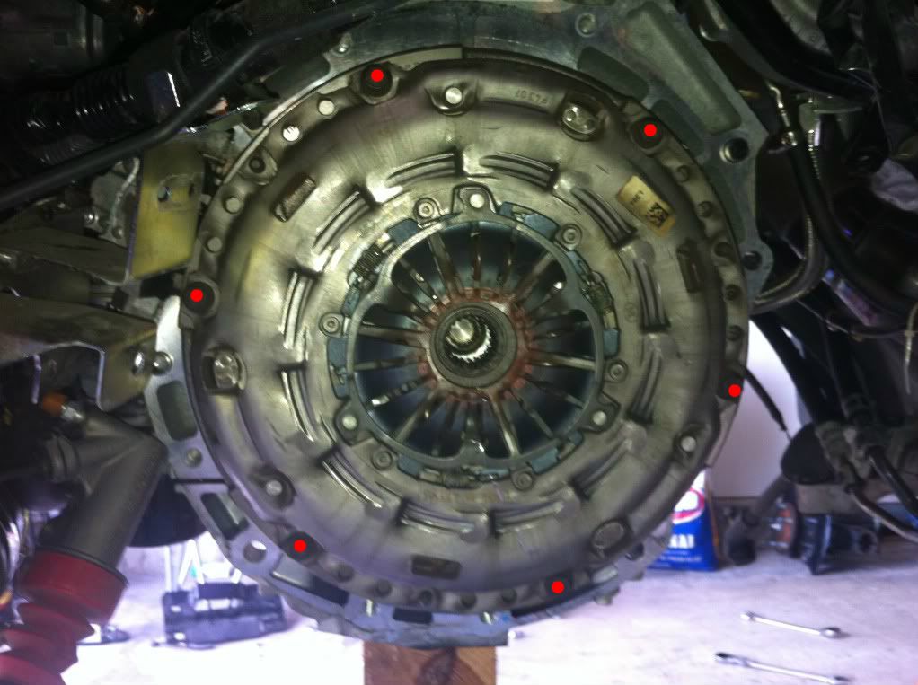
Now it’s time to remove the eleven 14mm bolts securing the bellhousing to the block:

Some are hard to get at, so use extensions, and swivel sockets:


Keep the bolts organized as you remove them, so you know where they go upon re-installing:

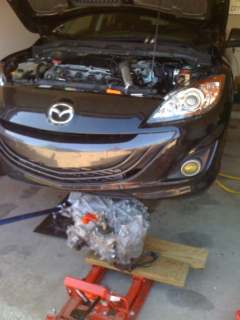
Yay! Now with all the bellhousing bolts removed, it’s time to get this extremely heavy trans out of the way. Being by lowering the jacks supporting the motor and the trans, in conjunction, to clear the trans from the frame. Use a pry bar to pry the trans away from the block, do this evenly around the bellhousing:

Keep working the trans away from the engine, by pulling it from the wheel well on left side of the car. Once the input shaft is slid out from the clutch assembly, and the trans is free from everything, lower the trans from the car:


This was done on a genpu, the gen1 requires the exactly the same procedures. This is meant to be a helpful walk through for doing a clutch swap on a MS3. This job should be performed ONLY BY PROFFECIONAL EXPERIENCED TECHNICIANS. I’m not liable for any mistakes you make, following this guide, which is probably not 100% accurate. This is probably a 12hr job according to Mazda, but it can be accomplished in <5hrs if you know what you’re doing.
Tools Required:
Socket Wrenches
Socket Sizes Used Most:
10mm
12mm
14mm
17mm
19mm
21mm
24mm
Ratcheting Wrenches(not necessary, but helpful):
10mm
12mm
14mm
17mm
Torque Wrenches
A Decent Screwdriver Set
Pry-Bars
Very Tall Jack Stands or a Lift
Transmission or Motorcycle Jack
Good Set of Pliers
Various Pieces of Wood
Hammers
Other Miscellaneous Hardware:
Brake-Clean
Grease
Thread-Lock
New Flywheel Bolts
New Trans Fluid
Rags, Towels, etc.
Coat Hangers, Rope, Wire, etc.
Drain Pan
Die-Grinder
Air Tools, Impact Guns
Piece of cardboard, and marker(to keep track of bolts)
Recommended to Replace:
Flywheel Bolts
Driveshaft Seals
Driveshaft C-Clip(only 1)
First, start by jacking the car in the air, or using a lift if you have one.
Begin by removing the undertray, front wheels, intake, battery, battery box, ECU, basically everything above the transmission.
Remove the brackets for the wiring harness and shift cables on the top of the trans, there is 3 brackets show here, all are being held on by 2 bolts IIRC:
Unbolt the coolant hard pipe running above the trans, as to access the trans bolts later, it’s held on by one 10mm nut on the front of the engine above the starter, and one 10mm bolt above the bellhousing towards the back of the engine:
Unclip the electrical connectors from the trans, located on a bracket on the front of the engine:
Remove the slave cylinder, from the bellhousing, two 12mm bolts, no need to remove the slave from the fluid line:
Next, drain all the trans fluid. Crack the fill plug first, just to make sure it will come out later. The fill plug is located on the front of the trans and, drain plug is located on the side of the trans, shown here
Fill:
Drain:
Now begin tearing into the brakes and suspension. Remove the front calipers, held on by two 17mm bolts, and remove the rotors. Hang the calipers by the springs with some rope/wire.
Now remove the tie-rod safety pin then the 14mm nut:
Put the nut on the stud, and whack the nut till the tie rod is free from the knuckle:
Remove the upper sway-bar end-link nut, remove the end-link from the strut and put the nut on it, so you don’t lose it(14mm and some metric hex key size… I just zip these off with an impact, since they’re usually rusted to shit and don’t want to come off. If all else fails, cut the end-link off and buy new ones):
Remove the lower ball-joint bolt nut(14mm):
Remove the strut bolt(17mm):
It’s now time to free the strut from the knuckle. First take out a big hammer and pound on the knuckle shown here:
Do this until the knuckle moves down about 1cm. This will allow you now to pry the knuckle open and slide it off the strut. It needs to go down about 1cm, because the strut has a protruding piece of metal as to align it in the knuckle. Now you take some random piece of metal roughly ¼” thick and place it where the strut bolt goes. I’ve used this tiny wrench for my air grinder, as well as big washers, or pieces of metal I have laying around. Thread in the strut bolt the opposite way so it can press up against the piece of metal, effectively prying the knuckle open:
Take a pry bar and pry down on the knuckle to free it from the strut:
Thanks Daniel “silvapain” for this trick
Now it’s time to separate the lower ball joint from the knuckle. I’m sure with Mazda’s special tool, or a ball joint separator, it would be easier, but it can be done pretty simply with other methods. With the bolt out, the ball joint should come right out of the knuckle, but it being a very tight fit and some corrosion can lead to it being a bit difficult.
Support the hub with a jack-stand.
Then take a hammer and start pounding on the lower control arm, around where the ball joint is. Work at it till the ball joint is almost free. Use a pry bar, or lift up on the knuckle, to remove the knuckle.
Now that the hub/knuckle assembly is removed from the surrounding suspension components, it’s time to remove the axles.
We’ll start with the right axle, there is a joint shaft bracket that needs to be unbolted from the block, held in by 3 bolts.
Here’s a better pic of the joint shaft bracket, and it’s location:
Now the axle can be removed from the transmission. It helps to have a friend hold the axle level, while you can pry the axle out. The prying actions is as goes: use a pry bar, and with a jerking motion pry against the raised edge of the axle, in short bursts, to literally pop the axle out of the trans.
Once the axle/hub assembly is removed, from the trans, set it aside.
Do the same on the left side of the vehicle, and pop the axle out.
Some people say it’s not necessary to remove the subframe to pull the trans. It honestly does not need to be removed, I’ve done a clutch job before with the subframe in place. However, you will save yourself many hours of frustration, by removing it. Why? A portion of the subframe site right underneath the differential, and you’ll spend more time trying to wiggle the trans out of a very tight space. Plus the subframe takes 15min to remove.
Begin with the cross bar behind the subframe, IIRC this is where the bolts are located. The 14mm bolts shown in green, the 14mm nuts shown in yellow, and the one 10mm bolt that supports the fuel line shield portion of the cross bar in red:
Unhook the rubber exhaust hangers that connect the exhaust to the subframe, location in green:
Remove the heat shield on the powersteering rack(red arrow), three 10mm bolts. Then unbolt the powersteering rack from the subframe, three 19mm bolts(shown in green):
Here’s a pic of how to get the center bolt, from the rear of the car:
Here’s a pic from the shop manual:
Now with the rack unbolted, use bungee cords or zip ties, to secure the rack to the exhaust so it doesn’t fall with the subframe.
Unbolt the RMM from the trans:
Now it’s time to unbolt the subframe from the car. CAUTION! The subframe is heavy, support it on jacks/jackstands and have a friend on each side ready to pull it out, once unbolted from the vehicle.
There are 4 main bolts(front 19mm, rear 17mm), indicated in this pic:
Use extensions through the holes in the LCAs to get at the front two bolts:
Remove the 12mm bolts of the support brackets, shown in green, then remove the 17mm subframe bolt, shown in red. Do the same on the other side.
Now that the subframe is detached from the vehicle, lower it slowly, making sure everything is disconnected, and move it from underneath the vehicle. You’ll have to move the FSB/endlinks and tie-rods around so they don’t get caught up on each other.
Time to remove the trans mount. First support the engine as well as trans with whatever methods you have, leave room to remove the lover bellhousing bolts later, or skip a few steps, and pull out the lower bolts now:
This car had a CP-E trans mount at the time of this install. If you have a different aftermarket mount, refer to the supplier instructions, on how to remove it. Here’s how to remove the OEM mount.
Begin with the battery support, held in by two 10mm bolts(pink), and four 17mm bolts(blue).
Next remove the 17mm bolt(red), and pull out the top portion of the mount.
Unbolt the three 17mm bolts/nuts(green), and remove the lower portion of the mount.
For better pics, refer to Jamie’s site: http://jamesbaroneracing.com/support/JBR MAZDA 3 & MAZDASPEED 3 Transmission Mount Installation Instructions.pdf
Now it’s time to remove the eleven 14mm bolts securing the bellhousing to the block:
Some are hard to get at, so use extensions, and swivel sockets:
Keep the bolts organized as you remove them, so you know where they go upon re-installing:
Yay! Now with all the bellhousing bolts removed, it’s time to get this extremely heavy trans out of the way. Being by lowering the jacks supporting the motor and the trans, in conjunction, to clear the trans from the frame. Use a pry bar to pry the trans away from the block, do this evenly around the bellhousing:
Keep working the trans away from the engine, by pulling it from the wheel well on left side of the car. Once the input shaft is slid out from the clutch assembly, and the trans is free from everything, lower the trans from the car: