Matt@DamondMotorsports
Approved Vendor
How to replace MS6 transfer case
To begin, this how-to shows how to replace the transfer case, without removing the subframe, just dropping it a little. If I were to do this again, I would remove the subframe completely, just for easier access getting the TC out of and into the car, and can save time.
Tools needed:
Socket wrench:
10mm
12mm
14mm
17mm
19mm
19mm deep socket
21mm
23mm
25mm or 26mm?
Many extensions
Swivel sockets
Breaker bar
TQ wrench
Wrenches:
14mm
17mm
Allens:
5mm
6mm
10mm
Screwdrivers
Hammer
Sledge hammer
Brass bar
Pry bar
Special tools:
Coupler flange bar/brace
Pulley puller
Start by jacking up the car as high as possible, and supporting it on jackstands, or putting the car on a lift. If you don’t know how to properly do this, stop immediately and pay someone to work on your car.

Remove the front wheels, 21mm, and remove the undertray splash shield, 10mm.
Drain the transfer case of all fluids… or in our case metallic fluids with chunks of metal. First remove the 23mm fill plug, then the 24mm drain plug:

ALL OF THIS IS DONE ON THE PASSENGER SIDE OF THE CAR, UNLESS NOTED.
Remove the two brake caliper bracket bolts, 17mm. Hang caliper aside.

Remove the ABS/wheel speed sensor from the knuckle, and hang aside, two 12mm bolts:


Remove the sway bar endlink from the knuckle on both sides of the car, 14mm 5mm allen.
Remove the 2 lower ball joint nuts, 23mm. These are on tight, so get the breaker bar or impact gun ready.

Once the nuts are loose, put them slightly back on the ball joints, as to not damage the threads while hammering.
Hammer the nuts with a sledge, until the ball joint pops free. Once free, remove the nut, and pull the ball joint out from the knuckle.
Remove the 17mm ball joint nut atop the knuckle, use a 6mm allen to prevent it from spinning and not coming loose. Repeat the same hammering procedure as the lower ball joints to remove the top ball joint from the knuckle.

Remove the 17mm bolt and nut connecting the LCA to the strut cup(circled in green):

Remove the tie rod from the knuckles on both sides of the car, 17mm. Use same hammering procedure, as before:

Now the knuckle and axle assembly should be free of the suspension components, and the axle can be removed.
Pop the axle joint from the transfer case using a a hammer and brass bar… really wish we got a pic of this, but here’s how to do it:

Remove the axle from the car.
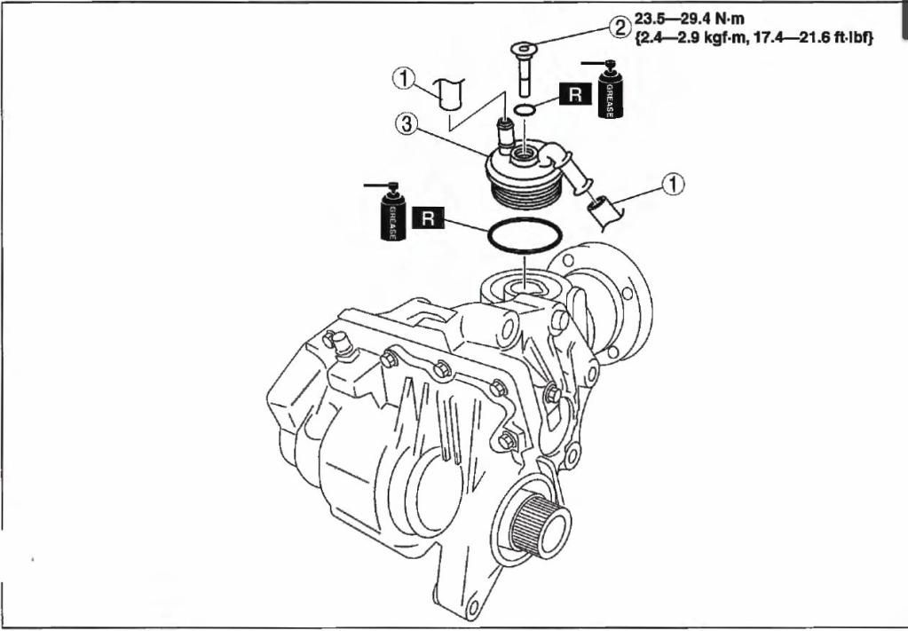
Remove the oil cooler bolt from the transfer case, 10mm allen, swivel socket, and lots of extensions:

Note the two rubber seals on the cooler, replace later if necessary. Support the cooler, up away from the TC, using a cable tie, or rope:

Pic shown with TC removed.
Remove the four 14mm nuts and bolts that attach the driveshaft to the transfer case. Let the driveshaft hang aside:

Remove any heat shields bolted to the TC, and catalytic converter bracket, if equipped.
Time to drop the subframe. If you wish to remove it completely, here’s a list of what else to remove:
Driverside 2 lower ball joints
Driverside 17mm bolt and nut connecting the LCA to the strut cup.
Power steering rack from subframe, two 19mm bolts, support rack to prevent it from dropping
Everything else will be outlined with dropping the subframe.
Remove the splash shields where they are attached to the subframe, five plastic clips IIRC:
Two on passengerside:

Three on driverside:

Remove the brackets holding the power steering lines to the subframe, four 10mm bolts(there may be an additional bolt in the area under the pump):


Unbolt the RMM from the transmission, 19mm:

Time to lower the subframe, get some jack stands, or blocks of wood to support the subfrome, once unbolted from the car.
Remove the four 17mm bolts that attach chassis brackets to the subframe(marked in red), then remove the two 19mm subframe nuts:


Remove the two bolts that support the front of the subframe, 19mm deep socket:


Support the subframe, or remove the subframe:

If you’ve removed the subframe, ignore this next step, if not get your coupler flange brace/bar, and pulley puller ready. The driveshaft flange needs to be removed in order to have clearance to maneuver the TC out of the car, since the flange will interfere with the subframe and downpipe exhaust.
Remove the 25mm or 26mm? nut connecting the flange to the TC.

Put the transmission in gear, connect your flange brace to the flange(I made one out of steel bar, with holes drilled 2 7/8” apart), get a breaker bar on the nut, and remove the nut. Simply putting the car into gear won’t work, the nut is on TIGHT, and I was able to turn the flange trying to loosen the nut.

Here’s a pic of my bar:

Remove the flange from the TC. Sometimes it will just slide right off. If not, use a pulley puller:

If you’ve decided to drop the subframe, ignore the above steps for pulling the flange.
Time to remove the TC.
Begin with removing the two 14mm bolts securing the TC to the TC bracket(blue). Then remove the four 14mm bolts securing the TC bracket to the block(yellow):

Using some extensions and swivel sockets, remove the two 17mm bolts that go into the TC from the driverside of the car:

Remove the three remaining 17mm bolts from the passangerside, there are two by the RMM, and one up top:


Pull the TC straight out from the transmission, careful not to damage the seal on the transmission, and remove the TC from the car(note: some transmission fluid will drain out from the transmission once the TC is removed),:

Install the TC.
Slide the TC into the transmission, being careful of the seal on the transmission, and turn the TC so that it goes into the alignment holes, and bolt holes align.
Install is reverse of removal. Don’t forget to put fluids in! Torque specs, and important info:
Note: TQ spec for the flange nut is 124-166FT-LBS, and the 14mm nuts for the drive shaft are 36.2-42.7FT-LBS


Will update soon with info for replacing the MS6 TC with a CX-7 TC... just waiting on pics.
To begin, this how-to shows how to replace the transfer case, without removing the subframe, just dropping it a little. If I were to do this again, I would remove the subframe completely, just for easier access getting the TC out of and into the car, and can save time.
Tools needed:
Socket wrench:
10mm
12mm
14mm
17mm
19mm
19mm deep socket
21mm
23mm
25mm or 26mm?
Many extensions
Swivel sockets
Breaker bar
TQ wrench
Wrenches:
14mm
17mm
Allens:
5mm
6mm
10mm
Screwdrivers
Hammer
Sledge hammer
Brass bar
Pry bar
Special tools:
Coupler flange bar/brace
Pulley puller
Start by jacking up the car as high as possible, and supporting it on jackstands, or putting the car on a lift. If you don’t know how to properly do this, stop immediately and pay someone to work on your car.
Remove the front wheels, 21mm, and remove the undertray splash shield, 10mm.
Drain the transfer case of all fluids… or in our case metallic fluids with chunks of metal. First remove the 23mm fill plug, then the 24mm drain plug:
ALL OF THIS IS DONE ON THE PASSENGER SIDE OF THE CAR, UNLESS NOTED.
Remove the two brake caliper bracket bolts, 17mm. Hang caliper aside.
Remove the ABS/wheel speed sensor from the knuckle, and hang aside, two 12mm bolts:
Remove the sway bar endlink from the knuckle on both sides of the car, 14mm 5mm allen.
Remove the 2 lower ball joint nuts, 23mm. These are on tight, so get the breaker bar or impact gun ready.
Once the nuts are loose, put them slightly back on the ball joints, as to not damage the threads while hammering.
Hammer the nuts with a sledge, until the ball joint pops free. Once free, remove the nut, and pull the ball joint out from the knuckle.
Remove the 17mm ball joint nut atop the knuckle, use a 6mm allen to prevent it from spinning and not coming loose. Repeat the same hammering procedure as the lower ball joints to remove the top ball joint from the knuckle.
Remove the 17mm bolt and nut connecting the LCA to the strut cup(circled in green):
Remove the tie rod from the knuckles on both sides of the car, 17mm. Use same hammering procedure, as before:
Now the knuckle and axle assembly should be free of the suspension components, and the axle can be removed.
Pop the axle joint from the transfer case using a a hammer and brass bar… really wish we got a pic of this, but here’s how to do it:
Remove the axle from the car.
Remove the oil cooler bolt from the transfer case, 10mm allen, swivel socket, and lots of extensions:
Note the two rubber seals on the cooler, replace later if necessary. Support the cooler, up away from the TC, using a cable tie, or rope:
Pic shown with TC removed.
Remove the four 14mm nuts and bolts that attach the driveshaft to the transfer case. Let the driveshaft hang aside:
Remove any heat shields bolted to the TC, and catalytic converter bracket, if equipped.
Time to drop the subframe. If you wish to remove it completely, here’s a list of what else to remove:
Driverside 2 lower ball joints
Driverside 17mm bolt and nut connecting the LCA to the strut cup.
Power steering rack from subframe, two 19mm bolts, support rack to prevent it from dropping
Everything else will be outlined with dropping the subframe.
Remove the splash shields where they are attached to the subframe, five plastic clips IIRC:
Two on passengerside:
Three on driverside:
Remove the brackets holding the power steering lines to the subframe, four 10mm bolts(there may be an additional bolt in the area under the pump):
Unbolt the RMM from the transmission, 19mm:
Time to lower the subframe, get some jack stands, or blocks of wood to support the subfrome, once unbolted from the car.
Remove the four 17mm bolts that attach chassis brackets to the subframe(marked in red), then remove the two 19mm subframe nuts:
Remove the two bolts that support the front of the subframe, 19mm deep socket:
Support the subframe, or remove the subframe:
If you’ve removed the subframe, ignore this next step, if not get your coupler flange brace/bar, and pulley puller ready. The driveshaft flange needs to be removed in order to have clearance to maneuver the TC out of the car, since the flange will interfere with the subframe and downpipe exhaust.
Remove the 25mm or 26mm? nut connecting the flange to the TC.
Put the transmission in gear, connect your flange brace to the flange(I made one out of steel bar, with holes drilled 2 7/8” apart), get a breaker bar on the nut, and remove the nut. Simply putting the car into gear won’t work, the nut is on TIGHT, and I was able to turn the flange trying to loosen the nut.
Here’s a pic of my bar:
Remove the flange from the TC. Sometimes it will just slide right off. If not, use a pulley puller:
If you’ve decided to drop the subframe, ignore the above steps for pulling the flange.
Time to remove the TC.
Begin with removing the two 14mm bolts securing the TC to the TC bracket(blue). Then remove the four 14mm bolts securing the TC bracket to the block(yellow):
Using some extensions and swivel sockets, remove the two 17mm bolts that go into the TC from the driverside of the car:
Remove the three remaining 17mm bolts from the passangerside, there are two by the RMM, and one up top:
Pull the TC straight out from the transmission, careful not to damage the seal on the transmission, and remove the TC from the car(note: some transmission fluid will drain out from the transmission once the TC is removed),:
Install the TC.
Slide the TC into the transmission, being careful of the seal on the transmission, and turn the TC so that it goes into the alignment holes, and bolt holes align.
Install is reverse of removal. Don’t forget to put fluids in! Torque specs, and important info:
Note: TQ spec for the flange nut is 124-166FT-LBS, and the 14mm nuts for the drive shaft are 36.2-42.7FT-LBS
Will update soon with info for replacing the MS6 TC with a CX-7 TC... just waiting on pics.