Navigation
Install the app
How to install the app on iOS
Follow along with the video below to see how to install our site as a web app on your home screen.
Note: This feature may not be available in some browsers.
More options
Style variation
You are using an out of date browser. It may not display this or other websites correctly.
You should upgrade or use an alternative browser.
You should upgrade or use an alternative browser.
Phate's Shop Build to Bring in a 5-Axis Mill!
- Thread starter Phate@2GFab
- Start date
- Watchers 11
Phate@2GFab
Grass-Roots Vendor
Alright. Seriously now. What the fuck do you plan on making
All in good time. I'm headed to Australia/NZ for a couple weeks, so this project gets paused after tomorrow.
Phate@2GFab
Grass-Roots Vendor
Air!
Finished!
I ran the conduit and wire for a 240V and 120V outlet. It's even quieter with the door on and sealed. 10/10, would do again.
The 120V outlet is just in case it needs a heater or heated wire. No use for it right now. I've only run the compressor at ~30°F, so I'll post up with any issues running when it gets even colder.
Phate@2GFab
Grass-Roots Vendor
Back to work!

If the compressor shed doesn't have one already that isn't visible in the pictures, I'd suggest to install a temperature controlled venting fan with circuitous & lined in & out ducts. I'd guess the compressor could get quite warm during summer which probably isn't a terminal problem but not great for long-term reliability.
Phate@2GFab
Grass-Roots Vendor
If the compressor shed doesn't have one already that isn't visible in the pictures, I'd suggest to install a temperature controlled venting fan with circuitous & lined in & out ducts. I'd guess the compressor could get quite warm during summer which probably isn't a terminal problem but not great for long-term reliability.
I looked at them but couldn't find one that seemed reliable enough to last. I do have two 10"x10" vents in it that should circulate the air pretty well while running. For winter, they're blocked off with some interior panels, but I'll pull them off once it's regularly above freezing. I will check shed temp once it gets hot, though. Adding a power vent is pretty minor after everything else, and I already have the 120V outlet available!
Really, I don't expect it to cycle much - 80 gallons is way more than I need but the compressor was a good deal. [Small plug for home depot - they allow you to stack military discount of 10% on top of their sales, which is nice for higher priced items. I just bought a new clamp meter using this same strategy!]

Phate@2GFab
Grass-Roots Vendor
Electrical!
Good update here - It's finished! And boy was it a lot of work. I just had one minor issue with the enclosed contactor and everything else went smoothly.
As a reminder of what's going on (it's a lot) from the previous post:
View attachment 30446
I pulled 4/0 to the big manual disconnect, and then to the RPC control panel.

The RPC panel is a nasty mess of wires because I wanted to leave a bit of wire in case the panel ever needed moved (I seriously hope not).


The motor wiring has a good bit going on. There's 9 wires to the motor, and 3 hots and a ground coming into the pecker head from the RPC panel. That's a lot of wires to wrangle. The motor connections all come terminated with ring terminals, and American Rotary supplies bolts/lock nuts for bolted connections. I'm not a fan, so let's do one better - Polaris gray connectors.
But first we need to run some wire to it. Because I'm using 2" conduit and the motor junction box only came with a hole large enough for something smaller than 2", so it's time we opened up the hole in our pecker box (heh). Luckily, we have the technology.


I wish I would have gotten pictures of how I clamped this thing to the front of the Bridgeport table - but that's what happened and I extended the gantry nearly all the way out and swung it to the side to reach. Use a boring head to cut it a little larger and we have something we can use.
Back to the wiring. I did wire it initially with the bolted connections just to make sure everything was functional. No sense in causing a fuss in case something was screwy with the motor. But then I went back and chopped those ring terminals off and used Polaris connectors:


Don't forget the vibration isolating feet!

Now that we have the manufactured 3rd leg for 3 phase (woohoo!), let's send it places. First, that's the enclosed contactor. This was fairly simple, I put it next to the RPC panel and ran the 3 hots/ground/2 monitor wires through. Here's the panels before the conduit went in (RPC panel on the right, enclosed contactor on the left):


Here's where I ran into the issue with the enclosed contactor. [For anyone searching this is an EC-90150 enclosed contactor. Information for these as-installed is nearly impossible to find so maybe this will help someone out.]
Voltage on the output side was FLAKY - and I could change it's behavior by moving the output side lugs. I made a video for American Rotary during troubleshooting, and they confirmed what I suspected - missing bolts between the contactor (upper) and overload monitor (lower) modules.

That was resolved with some bolts and belleville washers, and all is well now.
From the enclosed contactor we go to the transformer.


We have 3 contact areas - Input, taps, and outputs. Inputs aren't variable, so that's easy, just connect the incoming hots to X1, X2, and X3.
The outputs are fairly simple because I want 400/230V, so that means I need to connect H0-H4-H5-H6.
The taps require a little more thinking. Under no load conditions, I have higher than nominal (240V) voltage. But, based on experience pulling moderate load I know the voltage drops a few volts to just under 240V (typically). For right now, I've left the taps on the 240V setting, but this will be one thing I monitor very closely at first and may need to change.
If you watched the video, you can hear how quickly the motor starts up. It is seriously impressive that a 75hp motor tipping the scales at 600lbs comes to full speed in ~1 second. My clamp meter died somewhere between the end of racing season and now, so I haven't been able to check in-rush current. I'm really curious what that looks like for both the motor and transformer, so I have a new meter arriving tomorrow to measure it. I haven't tripped the 200A breaker, so the RPC soft start capacitors seem to be doing some work.
And things are...progressing") Taking some time to clean the coolant/conveyor systems, as well as the machine itself.
Taking some time to clean the coolant/conveyor systems, as well as the machine itself.


Good update here - It's finished! And boy was it a lot of work. I just had one minor issue with the enclosed contactor and everything else went smoothly.
As a reminder of what's going on (it's a lot) from the previous post:
View attachment 30446
I pulled 4/0 to the big manual disconnect, and then to the RPC control panel.
The RPC panel is a nasty mess of wires because I wanted to leave a bit of wire in case the panel ever needed moved (I seriously hope not).
The motor wiring has a good bit going on. There's 9 wires to the motor, and 3 hots and a ground coming into the pecker head from the RPC panel. That's a lot of wires to wrangle. The motor connections all come terminated with ring terminals, and American Rotary supplies bolts/lock nuts for bolted connections. I'm not a fan, so let's do one better - Polaris gray connectors.
But first we need to run some wire to it. Because I'm using 2" conduit and the motor junction box only came with a hole large enough for something smaller than 2", so it's time we opened up the hole in our pecker box (heh). Luckily, we have the technology.
I wish I would have gotten pictures of how I clamped this thing to the front of the Bridgeport table - but that's what happened and I extended the gantry nearly all the way out and swung it to the side to reach. Use a boring head to cut it a little larger and we have something we can use.
Back to the wiring. I did wire it initially with the bolted connections just to make sure everything was functional. No sense in causing a fuss in case something was screwy with the motor. But then I went back and chopped those ring terminals off and used Polaris connectors:
Don't forget the vibration isolating feet!
Now that we have the manufactured 3rd leg for 3 phase (woohoo!), let's send it places. First, that's the enclosed contactor. This was fairly simple, I put it next to the RPC panel and ran the 3 hots/ground/2 monitor wires through. Here's the panels before the conduit went in (RPC panel on the right, enclosed contactor on the left):
Here's where I ran into the issue with the enclosed contactor. [For anyone searching this is an EC-90150 enclosed contactor. Information for these as-installed is nearly impossible to find so maybe this will help someone out.]
Voltage on the output side was FLAKY - and I could change it's behavior by moving the output side lugs. I made a video for American Rotary during troubleshooting, and they confirmed what I suspected - missing bolts between the contactor (upper) and overload monitor (lower) modules.
That was resolved with some bolts and belleville washers, and all is well now.
From the enclosed contactor we go to the transformer.
We have 3 contact areas - Input, taps, and outputs. Inputs aren't variable, so that's easy, just connect the incoming hots to X1, X2, and X3.
The outputs are fairly simple because I want 400/230V, so that means I need to connect H0-H4-H5-H6.
The taps require a little more thinking. Under no load conditions, I have higher than nominal (240V) voltage. But, based on experience pulling moderate load I know the voltage drops a few volts to just under 240V (typically). For right now, I've left the taps on the 240V setting, but this will be one thing I monitor very closely at first and may need to change.
If you watched the video, you can hear how quickly the motor starts up. It is seriously impressive that a 75hp motor tipping the scales at 600lbs comes to full speed in ~1 second. My clamp meter died somewhere between the end of racing season and now, so I haven't been able to check in-rush current. I'm really curious what that looks like for both the motor and transformer, so I have a new meter arriving tomorrow to measure it. I haven't tripped the 200A breaker, so the RPC soft start capacitors seem to be doing some work.
And things are...progressing
Taking some time to clean the coolant/conveyor systems, as well as the machine itself. I assume you checked the battery in the clamp meter?
Awafrican
Moderator
ooh I hope he didn't. lolI assume you checked the battery in the clamp meter?
Phate@2GFab
Grass-Roots Vendor
I assume you checked the battery in the clamp meter?
Lol yeah. It's showing overload even when there's no wire in the clamp. I used this as an excuse to upgrade, of course - I bought the old one primarily for DC testing when I built my LiFePO4 battery for the 6 many years ago, so it was bare bones and wasn't true RMS for AC current.
I ordered a Fluke 378FC because it has some handy features for 3-phase. Conveniently on sale right now at HD so another stacked discount.
Phate@2GFab
Grass-Roots Vendor
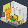
So all of this has been to land a CNC mill. I've been wanting to get one for a long time, but several months ago I made the decision to go all in on this and do it 'right'. I knew I wanted a 5-axis machine, and my biggest constraint is my shop's threshold height for actually getting a machine in.
Ultimately, I decided on a DMG DMU 50. Then it was just a matter of finding one with the right options, a reasonable number of hours, maintenance records, etc etc...just like buying a used car. I ended up finding one that was a super late add to an auction near where I grew up, and it seemed to check all the boxes and it came with a whole bunch of tooling. I went down to check it out before the auction went live and discussed its history with the company and with DMG. Everything seemed to check out, and the only downside to this machine is that it is incredibly dirty due to the environment it was in (old school machine shop with oil in the air). It also came with every manual imaginable so that was a big plus as well.
I'm still in the process of cleaning it up, but at this point I've powered it on and everything seems ok!


![20241122_094822[1].jpg](https://www.mazdaspeeds.org/data/attachments/30/30847-304405ca1ea96b3bda64f35d0514ff5b.jpg?hash=MEQFyh6paz "20241122_094822[1].jpg")
12k lbs of fine German iron and granite
XYZ Travels of 19.7" x 17.7" x 15.7"
HSK-A63 spindle - 18k RPM, 47hp
Siemens 840d controller
Through Spindle coolant (40 bar)
30 tool magazine
BLUM laser tool measurement system
I'm probably still a few weeks out from making chips, but I'm making progress with it.
Pretty much anything out of any material lol.
Ultimately, I decided on a DMG DMU 50. Then it was just a matter of finding one with the right options, a reasonable number of hours, maintenance records, etc etc...just like buying a used car. I ended up finding one that was a super late add to an auction near where I grew up, and it seemed to check all the boxes and it came with a whole bunch of tooling. I went down to check it out before the auction went live and discussed its history with the company and with DMG. Everything seemed to check out, and the only downside to this machine is that it is incredibly dirty due to the environment it was in (old school machine shop with oil in the air). It also came with every manual imaginable so that was a big plus as well.
I'm still in the process of cleaning it up, but at this point I've powered it on and everything seems ok!
12k lbs of fine German iron and granite
XYZ Travels of 19.7" x 17.7" x 15.7"
HSK-A63 spindle - 18k RPM, 47hp
Siemens 840d controller
Through Spindle coolant (40 bar)
30 tool magazine
BLUM laser tool measurement system
I'm probably still a few weeks out from making chips, but I'm making progress with it.
Alright. Seriously now. What the fuck do you plan on making
Pretty much anything out of any material lol.
Last edited by a moderator:
with those travels you really can make almost anything
phate
Motorhead
Is there any concern of freezing up the compressor (when its outdoors) during winter time?
An update on this since it seems we're past the coldest part of winter. I've been using the compressor pretty consistently the past couple weeks, with weather down to ~0°F and it's had no problems starting up.
Phate@2GFab
Grass-Roots Vendor
Update for the mill - it's been function tested and re-certified! It's well within factory allowance on all parameters (it is ridiculously good).
The mill has a tool measurement system inside the cabinet that was an option, so it wasn't in the machine model I had. I updated my machine CAD model with that hardware, and updated the kinematics to this machines particulars. Both the post processor and machine model are being validated by my Autodesk partner. I should have those back by the end of the week, then I'll cut some benchmarking parts to validate the post processor on the mill.
The mill has a tool measurement system inside the cabinet that was an option, so it wasn't in the machine model I had. I updated my machine CAD model with that hardware, and updated the kinematics to this machines particulars. Both the post processor and machine model are being validated by my Autodesk partner. I should have those back by the end of the week, then I'll cut some benchmarking parts to validate the post processor on the mill.
Attachments
Phate@2GFab
Grass-Roots Vendor
Doing some testing of the first program. The post processor seems to need some updates to change a few behaviors, but things are going well.
https://youtube.com/shorts/T8Tk5tJF8lQ?si=6Ay0_6LlGqI9sBOD
https://youtube.com/shorts/T8Tk5tJF8lQ?si=6Ay0_6LlGqI9sBOD
that thing is going to make some exquisite dildos.
Phate@2GFab
Grass-Roots Vendor
Start an only fans and just use this camera shot for every video
Phate@2GFab
Grass-Roots Vendor
Now that I have some hours running the DMG, there's a couple minor things that are going to change in the future.
Air wise, it consumes more air than expected. That's in part due to a couple small internal leaks, and there's a couple features above the base model that require air. So the compressor is running a lot, I'd say 50-60% of the time it's running. A screw compressor is probably in my future at some point.
With all of that air being consumed, the desiccant is working overtime to dry it. I get about 40 hours of run time on the DMG before it needs dried, but I'll be switching to a powered dryer very soon (and probably leave the filter system/desiccant in place to keep the air squeaky clean).
And some sweet simultaneous action:
https://youtube.com/shorts/9LTlpbxlrYQ?si=XxFM9T5x2foK2c02
Similar threads
- Replies
- 10
- Views
- 3K
- Replies
- 2
- Views
- 2K
- 0.00 star(s)
- Locked
- Replies
- 1
- Views
- 3K
- Replies
- 31
- Views
- 13K