I read it
Navigation
Install the app
How to install the app on iOS
Follow along with the video below to see how to install our site as a web app on your home screen.
Note: This feature may not be available in some browsers.
More options
Style variation
You are using an out of date browser. It may not display this or other websites correctly.
You should upgrade or use an alternative browser.
You should upgrade or use an alternative browser.
Mazda CX-7 Project
- Thread starter NinjaCustoms
- Start date
- Watchers 7
NinjaCustoms
Greenie Member
New Extra Project Update
As a tribute or reward to my readers/wievers
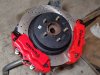
i completed the Brembo 18Z swap kit i will install with my sport suspension and lifetime zinc plated suspension parts.
Previously I uploaded my set for front
2x Brembo 18Z 6Pot calipers + 350mm gt rotors
and for the rear
2x Brembo 18Z 4Pot calioers + 330 mm gt rotors
This set is now expanded to
- Front stays the same
for rear it is now 4x Brembo 4 Pot Calipers
so 2 of them per axle which will make this car stop immediately after pressing brake pedal.
In a short time i will be buying new Brembo 25mm brake pump (stock is 20mm - piston size)
and I'll mount it to new servo mechanism along with thread reduction sockets from M12x1 (new pump thread size) to M10x1 (stock brake lines ending thread)
Also I'll be swapping elastic brake lines for forced steel wrapped teflone ones.
I will also swap my handbrake (line powered handbrake) for a hydraulic one that will let me slide Also it is better than this ugly stock one because these mazda oem handbrakes tend to loosen and not work over time.
Enjoy...
As a tribute or reward to my readers/wievers
i completed the Brembo 18Z swap kit i will install with my sport suspension and lifetime zinc plated suspension parts.
Previously I uploaded my set for front
2x Brembo 18Z 6Pot calipers + 350mm gt rotors
and for the rear
2x Brembo 18Z 4Pot calioers + 330 mm gt rotors
This set is now expanded to
- Front stays the same
for rear it is now 4x Brembo 4 Pot Calipers
so 2 of them per axle which will make this car stop immediately after pressing brake pedal.
In a short time i will be buying new Brembo 25mm brake pump (stock is 20mm - piston size)
and I'll mount it to new servo mechanism along with thread reduction sockets from M12x1 (new pump thread size) to M10x1 (stock brake lines ending thread)
Also I'll be swapping elastic brake lines for forced steel wrapped teflone ones.
I will also swap my handbrake (line powered handbrake) for a hydraulic one that will let me slide Also it is better than this ugly stock one because these mazda oem handbrakes tend to loosen and not work over time.
Enjoy...
Attachments
NinjaCustoms
Greenie Member
New small update
I'm done with the struts
If somebody is thinking how did I torqued this ,, impossible,, nut on top using only torque wrench.
The trick is simple.
Set your torque wrench for 60Nm , grab apx. 30cm of transport foil aka stretch from a roll an form some kind of rope by twisting it. wrap apx. 2 times on the strut piston rod and both end on the spring as hard as possible. The trick is this foil is very adhesive and by tightening it you create some kind of vice grip without damaging the strut. Then you can tighten the bolt without problems.
As always photo.
Attachments
NinjaCustoms
Greenie Member
New small update
I did is nearly as my first mod so some long time ago but I decided to upload it as next mod to this build or in case somebody would like to do it in own car.
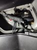
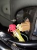
F1 Brake light .
Connections are (from device to taillight - color coding)
COLOR CODING FOR MAZDA ONLY!
YELLOW from f1 to RED WITH GREEN STRIPE
RED from f1 to BROWN WITH WHITE STRIPE
BLACK from f1 to GROUND , screw under any nut holding tail light
Make sure your ground cable connection to metal of chassis is good, i sulate all wiring separately to prevent any dangerous situation like water corrosion or shorting out due to damaged wires if u broke insulation during installation.
As always photos.
Small Warning - presented connection is for learning purposes, shortly after i soldered cabbles for steady connection (you don't need to).
P.S Excuse for dirty bumper, i took photos before detailing.
I did is nearly as my first mod so some long time ago but I decided to upload it as next mod to this build or in case somebody would like to do it in own car.
F1 Brake light .
Connections are (from device to taillight - color coding)
COLOR CODING FOR MAZDA ONLY!
YELLOW from f1 to RED WITH GREEN STRIPE
RED from f1 to BROWN WITH WHITE STRIPE
BLACK from f1 to GROUND , screw under any nut holding tail light
Make sure your ground cable connection to metal of chassis is good, i sulate all wiring separately to prevent any dangerous situation like water corrosion or shorting out due to damaged wires if u broke insulation during installation.
As always photos.
Small Warning - presented connection is for learning purposes, shortly after i soldered cabbles for steady connection (you don't need to).
P.S Excuse for dirty bumper, i took photos before detailing.
Attachments
NinjaCustoms
Greenie Member
New update,
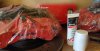
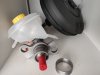
Today my Brembo M85 brake pump arrived, it is nearly twice as big as stock one so i think using industrial equipment such as lathe which i can use at my work will be needed.
Pump is in this beautiful red box next to my front big brake kit setup . Now i just need to adapt stock servo mechanism which i bought used in good shape.
I always buy another parts instead of taking apart existing ones i my vehicle because i habe better access when having another part and i can not worry about breaking sth.
In the next update i hope to post my adjusted servo and previously installed HKS Turbo Timer connections and config.
Attachments
NinjaCustoms
Greenie Member
New Announcement/Warning for other tuning boyz / detailers.
I made this mistake while cleaning wheels which caused them to debalance and provide vibrations on the steering wheel.
I am describin the proces for you to not make same mistake.
I generally use professional detailing chem which even has separate shelf in my garage and I'm not talking about single shelf i mean these nice storage like workshop rack.
I am using generally K2 PRO Series of detailing chem which is effective and not expensive af
For the wheel cleaning i used the ROTON which is a strong deionizer which cleaned those wheels to nearly new state .
The problem? Problem is the word ,, strong ,, .
As you may know or not wheels balance or as it is called in us or uk (not in my country which is poland) tire rotation process is a key of smooth ride.
In my situation as i mentioned i used one of the cleaners and left it to give him some time to ,,work,, while i took care with shampoo.
To the point.
I let it sit for maybe too long so one of the stick on weights from wheel removed itself when rinsed. I didn't notice it because be honest nobody counts those weights on each wheel but only think of them if any vibrations occur when driving.
The effect is i need to take off each of the wheel, remove every weight, give the inside a good clean if I'm removing wheels and rotate them and apply new wheels.
Unfortunately i need to drive to workshop for now but don't worry as i plan to have tuning shop im planning on buying one of these machines for tire rotation and tire removing machines next year along with sandblasting machine and tig welder .
Don't make the same little mistakes and take care of ur own car.
It may be harmless but In long term vibrations may cause you to loose cautious and even cause an accident which won't be good for you and your wallet.
Stay safe and updated, new posts incoming soon...
Edit:
Problem turned out to be bigger so you might be more cautious with cleaning wheels. It is better to take them of one by one clean , rinse, put and tighten.
In my case this chem turned out to block brake caliper so that's why the Front Right wheels was hot af. Now i will try to do the repair job without disengaging brake caliper from the line I'll try lubricate caliper guide , clean everything (in case I have spare caliper from rear suspension parts i bought to zinc plate and brembo swap) . Also I'll be probably changing brake pads because old ones might be melted or broke. In total i might remove caliper and restore it totally as my Brembo calipers.
Last Edit :
Also the debalance was caused not mainly by rims (weights are mostly ok , only 2 got off in washing process)
Another problem which wasn't good for my wallet because i wanted to waste money on upgrades not repairs and yes stock brake caliper was locked up and sized. I bought new , drained brake fluid installed new caliper, torqued it down to specs,140Nm with blue loctite 243. I needed to remove air bubbles from lines and it was done
Last edited:
NinjaCustoms
Greenie Member
New update
I'm finalizing Brake swap along with sport suspension.
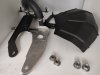
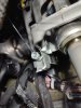
Now I'm working to get dual Brembo calipers per axle running so i designed new adapter for rear axle.
As stock this element which is mounted between hub and knuckle is thin and has obviously only one caliper mounting points.
I measured everything expanded holes a lot because Brembo rear calipers. Finding location for the second caliper was already ,,told,, by the knuckle because due to the structure there is only one place when after installing, calipers are :
-Not touching each other (always remember to install calipers facing air vents up)
-Not touching any suspension elements
Finally i need to cnc produce a set of these to fit my elements . Probably I'll make two sets.
As always, photo but showing only fitment not final effect.
I'm finalizing Brake swap along with sport suspension.
Now I'm working to get dual Brembo calipers per axle running so i designed new adapter for rear axle.
As stock this element which is mounted between hub and knuckle is thin and has obviously only one caliper mounting points.
I measured everything expanded holes a lot because Brembo rear calipers. Finding location for the second caliper was already ,,told,, by the knuckle because due to the structure there is only one place when after installing, calipers are :
-Not touching each other (always remember to install calipers facing air vents up)
-Not touching any suspension elements
Finally i need to cnc produce a set of these to fit my elements . Probably I'll make two sets.
As always, photo but showing only fitment not final effect.
Attachments
Why do you need two calipers?
NinjaCustoms
Greenie Member
Why do you need two calipers?
One is for normal braking and the another one will be connected to e-brake
NinjaCustoms
Greenie Member
New update
as brake swap is coming to the end nicely and everything fits here's the list for the CX-7 if you want same plug&play setup
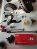
Brembo M85 054 Brake Pump
M 12x1 to M10x1 reductions for brake lines x2
Audi A6 C5 Brake fluid reservoir
Custom 49,85 to 45,75mm ring for pump fit
and of course old servo
all black items are painted with original black matte paint , when assembling use loctite threadlocker and sealant
what else you need?
Torque wrench
10, 12 , 14mm sockets
17 mm wrench
as always photos
Edit: Effect, what you want to see after assembly.
Notice that one silver piece is not on photo because it won't be assembled onto new piece (pump is blocking way ).
Last photo is presenting results
as brake swap is coming to the end nicely and everything fits here's the list for the CX-7 if you want same plug&play setup
Brembo M85 054 Brake Pump
M 12x1 to M10x1 reductions for brake lines x2
Audi A6 C5 Brake fluid reservoir
Custom 49,85 to 45,75mm ring for pump fit
and of course old servo
all black items are painted with original black matte paint , when assembling use loctite threadlocker and sealant
what else you need?
Torque wrench
10, 12 , 14mm sockets
17 mm wrench
as always photos
Edit: Effect, what you want to see after assembly.
Notice that one silver piece is not on photo because it won't be assembled onto new piece (pump is blocking way ).
Last photo is presenting results
Attachments

Last edited:
NinjaCustoms
Greenie Member
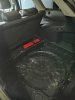
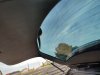
New update
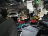
After Huuuuuuge break i found time to work on my car and i decided to do weight reduction in trunk space and to prepare it to some mods.
First i cleared some plastic. Then i reorganized wiring and hid it behind panels . (some tip- if you want to unscrew something, here the wiper motor to hide wires, and don't want to damage bolts visually ,put some foil in socket and everything looks as new). Then paint every panel not being painted by factory and cover those squares (which can be seen on photo) with some light soundeadning stiff foil (which is not shown on photo but it gives some detail to the job). and lastly remove soare tire , reorganize idk emergency triangle? and jack ect and you are 10 kilos lighter.
As always every photo i have taken.
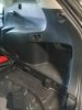
Attachments

NinjaCustoms
Greenie Member
New Update/ Advice
If you ever work on car project especially after watching thise how to ruin your car by stripping everything videos ,is quick show of how this makes no difference in stripping interior (I'm not taking about jacks , spare ect because these can be removed without breaking estetics)
Removing almost every part of trunk and interior as shown only made -5 kg which is nothing because removing spare and jack with unnecessary glovebox stuff gave me -20kg showed how much uglier car was made.
Everyone makes mistakes but i want to prevent yours so see it yourself.
Before (removed) ugly bare look no big gain
After (reinstall) slik oem sleeper look no loss
As always photos and as you can see I'm on my new property where I'll be building tune shop.
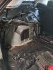
Attachments
NinjaCustoms
Greenie Member
New update/ old update
I promised to show u guys every previos mod i done that maybe someone wants to do but doesn't know how because fhere are no tutorials/instructions.
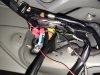
The last one is Turbo Timer from HKS .
What it does is after you turn off your car, your tirbine (IF IT IS TURBO'ED) is still spinning but the oil does not flow though it because you turned off the ignition.
What this beautiful device does is simply delay the process to not kill your turbo over time.
When installing some cars may have ready to buy plug n play harness which is easy but for Mazda of course you have the not easy way.
There are actually two methods of how to do it good and not to break everything.
1. Solder wires onto existing ones (not recommended because you may damage surroundings and you need to secure everything properly not to bur down your car.
2. RECOMMENDED - I call it vampire connectors.
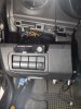
For this you need to check the HKS installation diagram for wires which is included in package and then dig into the internet to find the ,,color coding ,, which basically tells you which wire on the ignition and others does what .
The use the connectors to plug your wires , SECURE everything with iso. tape and shrink tubes. Then lay wires in elegant way and put everything back together.Find the ground place (best on the steering column - NOT ONTO THE MOVING PARTS). Last step is to find where to put the turbo timer unit itself.
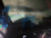
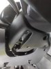
In The CX-7 case it looks like this on photos.
I made photos because I'm preparing a surprise update on wiring and i needed a professional clean look kf previous mods.
I promised to show u guys every previos mod i done that maybe someone wants to do but doesn't know how because fhere are no tutorials/instructions.
The last one is Turbo Timer from HKS .
What it does is after you turn off your car, your tirbine (IF IT IS TURBO'ED) is still spinning but the oil does not flow though it because you turned off the ignition.
What this beautiful device does is simply delay the process to not kill your turbo over time.
When installing some cars may have ready to buy plug n play harness which is easy but for Mazda of course you have the not easy way.
There are actually two methods of how to do it good and not to break everything.
1. Solder wires onto existing ones (not recommended because you may damage surroundings and you need to secure everything properly not to bur down your car.
2. RECOMMENDED - I call it vampire connectors.
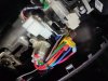
For this you need to check the HKS installation diagram for wires which is included in package and then dig into the internet to find the ,,color coding ,, which basically tells you which wire on the ignition and others does what .
The use the connectors to plug your wires , SECURE everything with iso. tape and shrink tubes. Then lay wires in elegant way and put everything back together.Find the ground place (best on the steering column - NOT ONTO THE MOVING PARTS). Last step is to find where to put the turbo timer unit itself.
In The CX-7 case it looks like this on photos.
I made photos because I'm preparing a surprise update on wiring and i needed a professional clean look kf previous mods.
Attachments
NinjaCustoms
Greenie Member
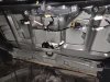
PART I
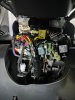
Promised update on wiring
Battery Relocation - from engine bay to trunk- how to do it right
First step is to disconnect battery mounts and pull it away.
Then you want to locate wires you want , in this case there is one cable on minus paired with ground one and two cabbles on plus.
For the CX-7
At this state you need to equip:
- min 6x Cable sleeve for 25mm² cabble
- 2x cabble sleeve for 50mm²
- Heat Shrink tubing, for whole project at least 2 meters
- insulation tape (black and red one for marking + and - and also equip the material one insulation tape which prevent cabble from abrasions
- nylon cabble braid 12mm at least 30meters
- main power kill switch - rally one from sparco
- ANL fuse 300A and casing
-3 pieces of 4m 25mm² cabble each
firs step is only difficult if you are not sure you want this mod, there is no way back after this step:
1. Cut cables from battery terminals
2.Prepare wires for connecting in sleeves
3.Take out at least 10mm of isolation from cabbles.
4.slide sleeves and crimp them with SPECIAL SLEEVE CRIMPING TOOL (fex Yato YT-22857)
5.Crimp prepared cabbles from the other side of the sleeve and crimp them.
6.On the connecting point put heat shrink tubing. Connection is approximately 5cm so you want at least 20cm of shrink tubing. Put 2 layers
7. then you want to wrap the whole cabble in material insulation tape .
8.Apply nylon cabble braid at the whole length and heat shrink the endings using heat shrink tubing for estehetics.
Next part.
1.Drill 15,5mm holes as shown on photos and smoothen them using dremel and fine sand paper.
2. Apply Zinc spray to prevent rusting
3. Apply Epoxide base coat
4. Apply Paint (matching your chassis, for me Mazda 35N - sparkling black)
5. Install rubber cabble gland (for ex. YT-06878) AFTER PAINT HARDENS FULLY!!
6.Pull the cabbles inside
7. Make space removing some of the interior pieces
At this point you can put in order every cabble for estehetics.
Optionally you can use exhaust wrap band for cabble protection in engine bay as i did . I'm planning additional turbo install so it is necessary protection.
That is everything i done in 3 days .
Next part (PART II) will include installation of main power kill switch, fuse and connecting battery terminals and placing battery itself in trunk.
Battery relocation gives you possibility of easy adding tuning stuff without worrying of how to lay additional wiring, weigh distribution and much more.
Unfortunately uploaded photos are not in wanted order but may be helpful for anyone trying to attempt same mod.
THIS MOD REQUIRES SPECIAL TOOLS AND EVEN CUSTOM CNC'ED DRILL EXTENSION TO BE ABLE TO DRILL THESE UNACCESSIBLE HOLES.


As always photos, stay tuned for part II.
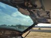
Promised update on wiring
Battery Relocation - from engine bay to trunk- how to do it right
First step is to disconnect battery mounts and pull it away.
Then you want to locate wires you want , in this case there is one cable on minus paired with ground one and two cabbles on plus.
For the CX-7
At this state you need to equip:
- min 6x Cable sleeve for 25mm² cabble
- 2x cabble sleeve for 50mm²
- Heat Shrink tubing, for whole project at least 2 meters
- insulation tape (black and red one for marking + and - and also equip the material one insulation tape which prevent cabble from abrasions
- nylon cabble braid 12mm at least 30meters
- main power kill switch - rally one from sparco
- ANL fuse 300A and casing
-3 pieces of 4m 25mm² cabble each
firs step is only difficult if you are not sure you want this mod, there is no way back after this step:
1. Cut cables from battery terminals
2.Prepare wires for connecting in sleeves
3.Take out at least 10mm of isolation from cabbles.
4.slide sleeves and crimp them with SPECIAL SLEEVE CRIMPING TOOL (fex Yato YT-22857)
5.Crimp prepared cabbles from the other side of the sleeve and crimp them.
6.On the connecting point put heat shrink tubing. Connection is approximately 5cm so you want at least 20cm of shrink tubing. Put 2 layers
7. then you want to wrap the whole cabble in material insulation tape .
8.Apply nylon cabble braid at the whole length and heat shrink the endings using heat shrink tubing for estehetics.
Next part.
1.Drill 15,5mm holes as shown on photos and smoothen them using dremel and fine sand paper.
2. Apply Zinc spray to prevent rusting
3. Apply Epoxide base coat
4. Apply Paint (matching your chassis, for me Mazda 35N - sparkling black)
5. Install rubber cabble gland (for ex. YT-06878) AFTER PAINT HARDENS FULLY!!
6.Pull the cabbles inside
7. Make space removing some of the interior pieces
At this point you can put in order every cabble for estehetics.
Optionally you can use exhaust wrap band for cabble protection in engine bay as i did . I'm planning additional turbo install so it is necessary protection.
That is everything i done in 3 days .
Next part (PART II) will include installation of main power kill switch, fuse and connecting battery terminals and placing battery itself in trunk.
Battery relocation gives you possibility of easy adding tuning stuff without worrying of how to lay additional wiring, weigh distribution and much more.
Unfortunately uploaded photos are not in wanted order but may be helpful for anyone trying to attempt same mod.
THIS MOD REQUIRES SPECIAL TOOLS AND EVEN CUSTOM CNC'ED DRILL EXTENSION TO BE ABLE TO DRILL THESE UNACCESSIBLE HOLES.
As always photos, stay tuned for part II.
Enki
Motorhead
IIRC turbo timers are really only needed on oil cooled turbos and even then, only if you beat on it and then shut it down relatively soon after.
Just cruising around getting food from the arches and back (with no WOT pulls) is highly unlikely to coke the oil in the turbo, especially modern oils.
Just cruising around getting food from the arches and back (with no WOT pulls) is highly unlikely to coke the oil in the turbo, especially modern oils.
NinjaCustoms
Greenie Member
I installed it because i do some trackdays, have oil cooling and always keeping+3k revs so it is necessary

NinjaCustoms
Greenie Member
Exactly, 2.2 I4, they will spool and yes, nitrous hit.
Custom ordered forged components are ,,in progress,, and it is a matter of 2-3 years when i'll unleash that beast
Custom ordered forged components are ,,in progress,, and it is a matter of 2-3 years when i'll unleash that beast
NinjaCustoms
Greenie Member
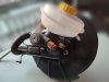
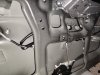
PART 2
Battery relocation
I only managed to lay cabbles through the prepared engine bay to the trunk.
There is a need to slightly trim and sand interior pieces (Just cutting useless and unnecessary material that may damage wires while assembling)


I managed to crimp one 50mm² ending on + terminal and choosed spot / marked cutting area for main power kill switch from sparco but it will be uploaded in part 3.
Stay tuned
Battery relocation
I only managed to lay cabbles through the prepared engine bay to the trunk.
There is a need to slightly trim and sand interior pieces (Just cutting useless and unnecessary material that may damage wires while assembling)
I managed to crimp one 50mm² ending on + terminal and choosed spot / marked cutting area for main power kill switch from sparco but it will be uploaded in part 3.
Stay tuned
NinjaCustoms
Greenie Member
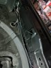
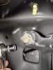
PART 3
Battery relocation
Mounting points are cut. I prepared new cabble from switch to positive terminal.Switch is mounted and the last thing to do is to connect fuse as close to the the battery as we can (max 30cm far from battery) , connect terminals then battery and finally mount everything back in new spot.
Similar threads
- Replies
- 2
- Views
- 482
- Replies
- 25
- Views
- 606
- Replies
- 3
- Views
- 380
- Replies
- 3
- Views
- 518