NinjaCustoms
Greenie Member
PART 4
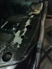
BATTERY RELOCATION
today I'm almost done, i preped mounting points and protected drilled area from rust with 3 layers.
Let's begin
First you want to mark holes and drill adequate sizes (in my case torx 12,9 8mmx25mm screws) for 8mm use 6,7mm drill and thread tap 8mm 1, 2 and 3'rd . Best if threaded with copper spray for smooth threading.


then prep the surface.
Give the area a good wioe with rust removing solvent and let it dry.

Then tape the surroundings with blue tape.
Apply epoxy primer.

And for better prep apply cavity wax to be sure no rust will ever come in tight spots.

Always remember to tape surroundings not to damage plastics. (don't forget to paint it in chassis colour)
Always use good ventilated area combined with mask.
Let everything a good day to dry. If it dries I'll make part 5.
BATTERY RELOCATION
today I'm almost done, i preped mounting points and protected drilled area from rust with 3 layers.
Let's begin
First you want to mark holes and drill adequate sizes (in my case torx 12,9 8mmx25mm screws) for 8mm use 6,7mm drill and thread tap 8mm 1, 2 and 3'rd . Best if threaded with copper spray for smooth threading.
then prep the surface.
Give the area a good wioe with rust removing solvent and let it dry.
Then tape the surroundings with blue tape.
Apply epoxy primer.
And for better prep apply cavity wax to be sure no rust will ever come in tight spots.
Always remember to tape surroundings not to damage plastics. (don't forget to paint it in chassis colour)
Always use good ventilated area combined with mask.
Let everything a good day to dry. If it dries I'll make part 5.