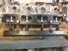
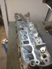
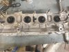
Whatever you do, don't port the floor of the ports. Only do the roof. Porting the floor will change the angle of airflow and can hurt performance more. Raising the roof is where you get increased volume.
It's ok to clean up the casting marks and stuff on the floor just don't change it too much.
It's ok to clean up the casting marks and stuff on the floor just don't change it too much.
")
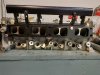
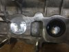

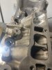
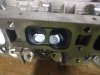
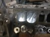
 This is honestly just the rough port and each one after got a bit better I felt like. I ended up porting it to where you can see both sides of the valve guide from that view. Not a huge difference but I feel that it will make it flow much better through there into the chamber.