Navigation
Install the app
How to install the app on iOS
Follow along with the video below to see how to install our site as a web app on your home screen.
Note: This feature may not be available in some browsers.
More options
Style variation
You are using an out of date browser. It may not display this or other websites correctly.
You should upgrade or use an alternative browser.
You should upgrade or use an alternative browser.
StreetSpeed’s DD 500+ MS6 Build
- Thread starter StreetSpeed6
- Start date
- Watchers 38
No it's not on the block yet. He left them unbolted because the head studs can't be taken off without pulling the cams anyway. He lightly engraved it instead of sharpie which I think is higher quality work as you won't lose it ever. It isn't enough to even be felt hardly either so it won't hurt it. They build race cars so I know they know what they're doing.Yeah I thought this was already bolted to the block and was like "wtf"
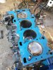
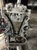
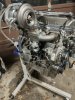
I finally made some progress on my engine and got the head installed and torqued down.

Small note- If you look closely the cross hatch is still good even at 30k miles!! (that's when you know your builder did a good job building it all)**

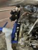
Got the cam caps all installed and torqued to 12ft-lbs with a dab of blue loctite for good measure.
I cleaned all of the mating surfaces for timing chain assembly and have everything ready to do the vvt job "tomorrow" (it's already 1am here).
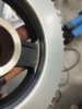
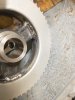
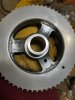
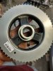
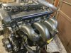
I purchased a new crank pulley as mine was old and nasty and wanted to start fresh. I prepped the joints and welded the timing ring onto the pulley as others have suggested for revving higher up (7800-8000). Seemed to turn out nicely considering all things.
Didn't want to switch my tig/stick over to the tig so I welded it with my 110v flux core welder which seemed to work out just fine imo for what it is. Little paint to keep it from rusting and viola!!
Small note- If you look closely the cross hatch is still good even at 30k miles!! (that's when you know your builder did a good job building it all)**
Got the cam caps all installed and torqued to 12ft-lbs with a dab of blue loctite for good measure.
I cleaned all of the mating surfaces for timing chain assembly and have everything ready to do the vvt job "tomorrow" (it's already 1am here).
I purchased a new crank pulley as mine was old and nasty and wanted to start fresh. I prepped the joints and welded the timing ring onto the pulley as others have suggested for revving higher up (7800-8000). Seemed to turn out nicely considering all things.
Didn't want to switch my tig/stick over to the tig so I welded it with my 110v flux core welder which seemed to work out just fine imo for what it is. Little paint to keep it from rusting and viola!!
Attachments
Do remember the bolt location for this @Sho because I am about to install the TC lolRemind me of the noise its making?
Buddy did a vvt job on his 6 and accidentally put one of the longer timing cover bolts in the wrong spot which was causing a knocking sound. Swapped the bolts out to their correct places and it stopped.
Pretty sure that's in the shop manual too
Awafrican
Moderator
It is...Pretty sure that's in the shop manual too
Edit: it's also in the threads about how to time your engine
Might just be that I strictly use my phone but I can't ever find stuff it seems. I have downloaded most of the shop manuals to my phone but it loads it sort of slow. Is there a method to which shop manuals (1,2,3,4,6 etc...) are for what purposes? I mean I assumed that info would've been in the mzr assembly.It is...
Edit: it's also in the threads about how to time your engine
Well I am just double checking a few things but am not having much luck. One thing I looked into was the position of the vvt solenoid sprocket.Metal member area...
Engine Workshop Manual L3 WITH TC
Is the engine generic one I keep handy. Just double checked on Android phone...its fast and while has MOST of the necessary steps. Its great for specific shortcut stuff.
I'm guessing you want this.
Couldn't really find an answer on it as I didn't know the orientation of it before. Now I have installed everything and am wondering if it was wrong and second guessing stuff. Just me worrying I guess but I don't want it to not be getting oil pressure and actually working and changing the timing properly otherwise my car will not make power easily at all.
Cfoldone
Silver Member
Easier way is with valve cover off, hpfp out. Take cam timing plate and rotate crank to align cams. See if tooth 20? Alignment to crank position sensor. Double-check again by cam plate removal rotate crank to now installed crank counterweight cheek bolt stop. See if again cams are aligned & tooth 20 Those three things are it.
That shop manual entry of the spot on VVT was confusing, it isn't important if the steps I outlined above are in time. I think it was for a VVT only repair by dealerships?
That shop manual entry of the spot on VVT was confusing, it isn't important if the steps I outlined above are in time. I think it was for a VVT only repair by dealerships?
I double checked after final tq of my crank bolt. Bumped the crank against the timing pin and the cam plate slipped right in and crank pulley is on the 20th tooth with the crank position sensor.Easier way is with valve cover off, hpfp out. Take cam timing plate and rotate crank to align cams. See if tooth 20? Alignment to crank position sensor. Double-check again by cam plate removal rotate crank to now installed crank counterweight cheek bolt stop. See if again cams are aligned & tooth 20 Those three things are it.
That shop manual entry of the spot on VVT was confusing, it isn't important if the steps I outlined above are in time. I think it was for a VVT only repair by dealerships?
Everything seems right so I won't worry about it! Thanks for your help man I appreciate it!
Awafrican
Moderator
I'm on here 95% of the time on my phone, download the complete shop manual rather than trying to search parts.Might just be that I strictly use my phone but I can't ever find stuff it seems. I have downloaded most of the shop manuals to my phone but it loads it sort of slow. Is there a method to which shop manuals (1,2,3,4,6 etc...) are for what purposes? I mean I assumed that info would've been in the mzr assembly.
Also remember google search "TDC pin site:mazdaspeeds.org" will search only the forms or you can try "timing" and it'll probably bring up the timing threads of where to place it too, whenever I find and link stiff for people that's usually what I do unless I have a thread book marked, they are also your friend.
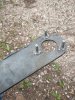
Engine is back together for the most part but needing to do some of the "bolt on" type stuff. Made a crank pulley holding tool that I figured I would share. Kind of wild looking and rough since I didn't take time to clean it up yet but it worked flawlessly!
It is made to set against the floor while on an engine stand so it holds the pulley still while doing the final 90 degrees after you have done the initial 75lb-ft and checked it is in time correctly.

For anyone wanting to build it on the cheap.
* 3/8" plate steel
* 36" long
* 3 3/4" wide tapered to 2.5"
* 1 1/2" center hole (for crank bolt)
* (3) m8-m10 size bolts cut 1 1/4" total length and welded.
Notes-- I used a white paint marker and the pulley laid on the tool to mark where to weld the bolts on. This will ensure they all touch the pulley together evenly.
It is made to set against the floor while on an engine stand so it holds the pulley still while doing the final 90 degrees after you have done the initial 75lb-ft and checked it is in time correctly.
For anyone wanting to build it on the cheap.
* 3/8" plate steel
* 36" long
* 3 3/4" wide tapered to 2.5"
* 1 1/2" center hole (for crank bolt)
* (3) m8-m10 size bolts cut 1 1/4" total length and welded.
Notes-- I used a white paint marker and the pulley laid on the tool to mark where to weld the bolts on. This will ensure they all touch the pulley together evenly.
Attachments
Well because my builder said that's what he has used a lot and it seems to do a great job. I hope it doesn't bite me but he does build engines a lotMay I ask why you used a felpro head gasket? And not oem or cometic which run $80-90 and are proven to work

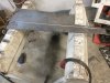
So here is a sneak peak of some of what I have been up to..... It's so sexy and NSFW lol jk I wanted to powder coat my valve cover and intake manifold but decided to wait until everything is working and plumbed in correctly etc.
") @SyntheticAtmosphere I'm sure you'll love the top mount BT action lol
@SyntheticAtmosphere I'm sure you'll love the top mount BT action lolIgnore the mess behind the beauty please lol It's a mess but I have cleaned up a bit and am just wanting to get this girl back on the road!
Attachments
What turbo and flange type is that?
It is a Pulsar version of the gtx3576r .82 a/r and is vband inlet and outlet. The manifold is t3 so I have an adapter that goes from t3 to vband it helped raise the turbo a bit and vband is much easier to unhook.What turbo and flange type is that?
Did you take that with a fish eye lens? Id say that wont fit under the hood -- HAHAHA!!!
Similar threads
- Replies
- 1
- Views
- 96
- Replies
- 6
- Views
- 300
- Replies
- 20
- Views
- 646
- Replies
- 6
- Views
- 779
- Replies
- 8
- Views
- 677