AWD Speed 3 Project - Halfmilespeed3

Thanks for the update.....glad to see the progress is coming along awesome stuff.
my question would be for the MS3 driver side motor mount, does it bolt right up to the MS6 trans? and Retain the MS3 shiffter cables?

From what I can tell: the driver side case half of the transmission is the same for MS3 and MS6. Therefore the TMM and shift cables bracket directly transfer like OEM.

The passenger side case half of the transmissions are different. The obvious difference is the Transfer Case connection but the less obvious is the RMM connection. I have not found any other differences that have caused issues. Even the slave cylinder mounting is the same so the MS3 slave cylinder transfers over
this is good news that the TMM transfer over and bolts right up.looking forward to see how the passenger side axle comes out
 
What a great Monday! Some goodies arrived today (both expected and not expected).

Little box is an AWD controller that integrates with the ECU and CAN data. Has its own software and programming logic.
Tote is a spare T-case that will get billet bearing caps
Fragile box is a surprise pack of whiskey that a friend sent me!
 

Attachments

  • 337825556_775996713788299_3513574223129154847_n (1).jpg
    337825556_775996713788299_3513574223129154847_n (1).jpg
    1.4 MB · Views: 47
What a great Monday! Some goodies arrived today (both expected and not expected).

Little box is an AWD controller that integrates with the ECU and CAN data. Has its own software and programming logic.
Tote is a spare T-case that will get billet bearing caps
Fragile box is a surprise pack of whiskey that a friend sent me!
can go wrong with some goodies and the whiskey just the added bonus lol dreaded monday's are a thing of the past
 
What a great Monday! Some goodies arrived today (both expected and not expected).

Little box is an AWD controller that integrates with the ECU and CAN data. Has its own software and programming logic.
Tote is a spare T-case that will get billet bearing caps
Fragile box is a surprise pack of whiskey that a friend sent me!
Smart choice man! Syvecs have very solid products and they very well known.
 
A couple updates over the weekend:
Finished up some assembly of the Radium FCST (Fuel Cell Surge Tank) system. Added the second fuel pick up in the surge tank for another external pump (running a MagnaFuel 525 for PI and a Quantum 380 for DI). Setup the "hellcat" 525 in the lift pump location to feed the surgetank and installed the level sensor. Need to order a filter sock for the lift pump still.
IMG_5611.JPG
IMG_5612.JPG

I then working on the filler neck/plumbing setup. While I could just use a cap on the tank itself, I wanted to keep a more OEM like setup and I didn't want to be required to remove the parachute, to open the hatch to then move the firewall cover to then fuel the cell...so I'm using the OEM location instead.
Now here is the best part. I was trying to use Radium's remote filler inlet/cap but was struggling...my buddy had the bright (and obvious) idea to use the OEM filler cap since it already fit...duh.
IMG_5616.JPG
But how do we connect the dots?
IMG_5613.JPG
So we cut nearly all of the OEM plumbing off and removed the flapper inside the filler so its jsut an open funnel now.
Using a 1.50" OD SS pipe with 6inch legs and 45deg bend and my plumbing and a bit of CAD (cardboard assisted design) I was able to get a good route that clears the tire and has a shallow slope to it.
IMG_5615.JPG
I cut a hole through the wheelwell and presto! Perfect routing.
IMG_5618.JPG
Now the Radium filler hose (1.50" ID) will fit over the SS pipe and run down tot he remote filler spout elbow on the tank (also Radium)

So how to cut the OEM filler plumbing?
IMG_5619.JPG
IMG_5620.JPG
Cut the OEM plumbing right below where it reduces in diameter. Measure to be sure but it should be right at or under 1.40" OD. You want a little bit of material left over to insert into the 1.50" OD Pipe for welding.
 
Next update from the weekend: The rocker arm suspension is no longer jsut a cool idea and CAD model!

Firstly, I had to remove the brackets that are spot welded and stitch welded to the tops of the shock towers in the rear of the car.
IMG_5621.JPG
This provided me access to the actual top of the shock tower and a flat open face to weld the crossmember end plates to.
IMG_5622.JPG
Next I hole saw cut out the tops to a larger 2-1/4" to provide clearance for the pushrod and rocker arm.

With the areas of welding prepped, I can get the crossmember and endplate into position.
IMG_5625.JPG
With a combination of measurements and "eyeballing it" I got the crossmember aligned with the shock towers and to the height I wanted so the rocker arm has nearly sufficient clearance at full droop. ( I later found out it was not enough but I can jsut trim the opening a bit more)
IMG_5626.JPG
With the crossmember endplate tacked in place I could move to the mounting brackets for the rocker arms and damper mounts.
IMG_5627.JPG
IMG_5628.JPG
The center damper mount was assembled with the hardware as it would be installed with the dampers so the width is correct and held in place while positioning. I found center on the crossmember, marked it and got the bracket tacked in place.

Now I could move to the rocker arm mounts
IMG_5629.JPG
Following my CAD model, I measured from the edge of the center damper mount to where the edge of the rocker mount was supposed to be. Marked that then placed the assembled rocker arm mount with rocker arm. Again tacking in place with the setup assembled helped to set the width and hold the structure togethor. Not pictured: I also used a clamp to the hold the bottom section of the mounts on the rocker arm tightly togethor.
With location set, I cycled the rocker arm to verify proper movement and function at the location. All was good minus the rocker arm needs and extra 0.25" or so of droop travel. Right now it is hitting the shock tower top so there will need to be more trimming.
I leveled the rocker arms to the center damper mount so they were on the same plane. Tacked and good to go!
Here is the final product:
IMG_5632.JPG

Next up I need to get the trailing arm push rod mounts tacked to the trailing arms and then work on the pushrod length.
Currently the entire crossmember can rotate in the endplate so i can control and set the rocker arm angle to match the angle of the pushrod at ride height. This is not super critical but it does help control forces going through the pivot bearings in the rocker arms.
 
A question to the Forum Engineers: Additional bracing for the crossmember
- I am planning to add bracing along the blue lines in the image. This is mainly to support the composite forces pushing downward in the center of the crossmember.
- I did specifically design the dampers at a shallow angle to reduce the downward force on the center but it will still be present and significant.

Now how strong are the shock towers themselves?
- Personally I think the OEM shock towers can handle the forces that will be put on them and they are now tied togethor. The force will be mainly vertically up. Add the center brace and I think it will be very strong.
- I've had some friends express concern that the shock towers are not strong enough and perhaps I should add some bracing to the shock tower itself or and a tube under the crossmember in parallel to the shock tower.

IMG_5632.JPG
 
I am not an engineer, but I think just looking at it, I would add that support for peace of mind.
 
so you are relying on the the stock shock tower to take the whole weight of the car, remember in the stock configuration the weight is on the springs which are supported by the subframe.

or are you keeping the stock spring location? i forget.

i would add the bracing you are proposing then i would also add a brace from the shock tower down to the same place as your other proposed brace.

what gauge and type of steel are your laser cut brackets made out of? eyeballing from these pictures it looks a bit lightweight for the forces it will see.

could you make the center bracket for the shock mounting taller to reduce the vertical loading?
 
The subframe did not actually support the weight. the top of the spring rests against the "chassis rail" and the subframe is just sandwiched between them.

Tubing is 1.75x0.120w DOM and end plates are 0.135" 1008
I should also note that the crossmember is nested in the endplate, not just face welded.

I could raise the center damper mounting but that would affect my damper vs rocker arm angles and thus affect motion ratios a bit.
To do that correctly, the rocker arm design would have to change which is not going to happen.

A vertical section of tubing directly under the rocker arm would not add that much more weight and would add alot of strength directly to the cage base plate which is welded directly to the "chassis rail" above the OEM spring location.
 
Is it a thing with cars to structurally adhese parts (so fay) and then weld (fillet) the rest of the structure together?

Even if you are releasing the adhesive fay (so just using it as a shim) you might get a little more strength out of the joint that way.
 
That makes sense that the subframe sits on the chassis at the spring location, I just haven't pulled one off so I didn't know

Are you keeping the spring in that location?
 
That makes sense that the subframe sits on the chassis at the spring location, I just haven't pulled one off so I didn't know

Are you keeping the spring in that location?

Spring will be on the damper itself. Makes the preload adjustments much simpler along with other things.
The pushrod uses LH/RH spherical rod ends so that will be the height adjustment for corner balancing.
 
More updates from lastnight:
A buddy and I prepped the trailing arms for the pushrod mounts last night and got them tacked in place.
IMG_5676.JPG
Mazdaspeed-3-AWD-Swap-Pushrod-1.JPG
Mazdaspeed-3-AWD-Swap-Pushrod-2.JPG
Mazdaspeed-3-AWD-Swap-Cantilever-4.JPG

The cleaning and paint removal was kinda of a pain because it was just difficult to get in the tight corners but we got it handled.
IMG_5680.JPG

Currently tacked in place plus alittle bit before I realized how late it was and wrapped up for the night.

I did check push rod lengths with tires at full bump and rocker arm at full bump. 16-3/4" length.
I'll shorten that a a bit to 16-1/4" rod length so the LH/RH threads of the rod ends have some adjustment range but still good thread engagement.
 
Last edited:
A couple updates over the weekend:
Finished up some assembly of the Radium FCST (Fuel Cell Surge Tank) system. Added the second fuel pick up in the surge tank for another external pump (running a MagnaFuel 525 for PI and a Quantum 380 for DI). Setup the "hellcat" 525 in the lift pump location to feed the surgetank and installed the level sensor. Need to order a filter sock for the lift pump still.
View attachment 25040
View attachment 25041

I then working on the filler neck/plumbing setup. While I could just use a cap on the tank itself, I wanted to keep a more OEM like setup and I didn't want to be required to remove the parachute, to open the hatch to then move the firewall cover to then fuel the cell...so I'm using the OEM location instead.
Now here is the best part. I was trying to use Radium's remote filler inlet/cap but was struggling...my buddy had the bright (and obvious) idea to use the OEM filler cap since it already fit...duh.
View attachment 25042
But how do we connect the dots?
View attachment 25043
So we cut nearly all of the OEM plumbing off and removed the flapper inside the filler so its jsut an open funnel now.
Using a 1.50" OD SS pipe with 6inch legs and 45deg bend and my plumbing and a bit of CAD (cardboard assisted design) I was able to get a good route that clears the tire and has a shallow slope to it.
View attachment 25044
I cut a hole through the wheelwell and presto! Perfect routing.
View attachment 25045
Now the Radium filler hose (1.50" ID) will fit over the SS pipe and run down tot he remote filler spout elbow on the tank (also Radium)

So how to cut the OEM filler plumbing?
View attachment 25046
View attachment 25047
Cut the OEM plumbing right below where it reduces in diameter. Measure to be sure but it should be right at or under 1.40" OD. You want a little bit of material left over to insert into the 1.50" OD Pipe for welding.
the radium fuel setup looks awesome and came out pretty good.retaining the oem filler makes sense and easy to fill up on the track.
looking forward for more updates
 
Another Update:
Rear axles from DSS arrived.
View attachment 24729
These are "700hp" rated axles per DSS. Doggo approved

View attachment 24730 View attachment 24731
View attachment 24733
Axle fitment is good with lots of length adjustment range for more or less camber than the current -2.5 degrees.
I also opted to have the wheel speed rings placed on the inboard side of the axles so i don't have to fight fitting a speed sensor inside/through the MS3 trailing arms. I will make brackets off of the rear diff mount to mount the speed sensors.
I have ordered speed6 wheels speed sensors for the rear. I will need to change the electrical connector though. It seems the MS3 is unique in its design vs the speed6 and CX7.

View attachment 24736
The blue part is the final design for the CX7 front diff mounts. Those are in machining now and I should have them in a couple weeks.
What are the overall length of the DSS axles?
 
More updates and lots has happened:
Did a bunch of welding (these are not final but are the images I seem to have). By no means am i a professional or even great welder so they are not pretty but they get the job down and will get cleaned up and painted either way.
IMG_5700.JPG IMG_5702.JPG IMG_5703.JPG IMG_5705.JPG IMG_5706.JPG
 
I also worked on alot of electrical and fuel plumbing recently:

Electrical:
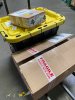
So I moved the battery location to passenger side in front of the rear axle centerline. This did not requirement to change my cables much and helps with weight distribution a bit more being passenger side.
The AntiGravity Battery can be mounted in any orientation which helped alot and the MELE box is solid so its bolted directly to the chassis.
IMG_5798.JPG
You can also see here, my rear mounted fuse/relay box so it also gets power directly from the battery and will power the entire fuel system and Syvecs AWD controller in the back of the car. The OEM "signal" for the OEM fuel lift pump will "signal" the relays for each pump:
- 525LPH lift pump inside the cell filling the surge tank which feeds two external pumps
- 380LPH inline 044 style pump feeding DI only
- 525LPH geared MagnaFuel pump feeding the PI only
So this way the entire system is on/off by control of the Motec and on one leading circuit with each getting their own dedicated 20amp relay

I also added in a rear exterior kill switch to meet NHRA requirements. This did require some changes/additions to my cables and such. I had to get a little creative making "T" splice with 2awg cable. Overall it came out very nice, dare I say OEM level on that splice.
IMG_5799.JPG IMG_5800.JPG

Now to the fuel system plumbing. Both external pump are under the chassis floorboard where the OEM fuel tank was previously sitting.
IMG_5764.JPG
- MagnaFuel 525 driver side with dedicated 10AN feed line then feeding a 10AN hardline that comes up into the engine bay. There is also a parallel 8AN hardline for the PI return that returns directly into the surge tank.
- Quantum 380 passenger side with a dedicated 10AN feed line that is plumbed into the OEM hardline feeding the HPFP.
I am well aware of how open and vulnerable everything is. Both pumps are quite high up but exposed to the elements and the driveshaft. I plan to create a driveshaft shield to protect the pumps and hard lines. A later down the road flat bottom aero will add more protection.

Next are the hard lines in the engine bay. I'll admit this is a little more haphazard than I would prefer but I am running out of time. They are secure, isolated, and easy to access with everything in the engine bay.
IMG_6020.JPG

Lastly is the fuel cell setup. With the pumps located I was able to setup the bulkhead fittings and plump the two feeds and one return line.
IMG_5802.JPG
The fill hose is also cut to length. The filler neck will get secured once a mounting plate shows up.
 
Back
Top