Navigation
Install the app
How to install the app on iOS
Follow along with the video below to see how to install our site as a web app on your home screen.
Note: This feature may not be available in some browsers.
More options
Style variation
You are using an out of date browser. It may not display this or other websites correctly.
You should upgrade or use an alternative browser.
You should upgrade or use an alternative browser.
How To: Mazdaspeed 3/Mazdaspeed 6/CX-7 VVT The Roku Way
- Thread starter Rokusek
- Start date
- Watchers 48
TheAcumen
Greenie N00B Member
I might be able to sneak into the garage this weekend and get the disassembly done but it's most likely gonna be next weekend.No worries, just don't see a point in replacing it if it is not necessary. No harm in it. But by no means is it required. I have a few things I need to update on the OP still for some clarification.
How far out are you being able to do this?
I might be able to sneak into the garage this weekend and get the disassembly done but it's most likely gonna be next weekend.
Ok, I'm gonna send you my cell, that way if you run into a snag you have instant contact.
@TheAcumen Just remember if you get someone's number from here dick pics are expected.Ok, I'm gonna send you my cell, that way if you run into a snag you have instant contact.
Tapasuck, it sucks a lot.
@TheAcumen Just remember if you get someone's number from here dick pics are expected.
Tapasuck, it sucks a lot.
You never sent me dick pics...

Staying on topic:
One of the things I wanted to address before you start (and I will fix the OP this weekend)
DO NOT BREAK TIMING until you have put the crank at TDC and place your Cam tool.
After doing this on my 6 last weekend, reading the OP and shop manual I realized it was something that was wrong on my wording.
Anyways, you have my number, please do not hesitate to call with questions.
TheAcumen
Greenie N00B Member
I think I'll just stand naked over a mirror and send that? You get a bit of everything.@TheAcumen Just remember if you get someone's number from here dick pics are expected.
Tapasuck, it sucks a lot.
But for real @Rokusek, dude I owe you big time! I can send you some belly button lint or old cheese? Never in my life did I image a forum interaction that went like this. You are one hell of a guy for the amount of time you gave to me over the past few days. I hope I can help you some day or at least pay it forward.
I think I'll just stand naked over a mirror and send that? You get a bit of everything.
But for real @Rokusek, dude I owe you big time! I can send you some belly button lint or old cheese? Never in my life did I image a forum interaction that went like this. You are one hell of a guy for the amount of time you gave to me over the past few days. I hope I can help you some day or at least pay it forward.
I like belly button lint...
All I ask is to pay it forward. This community used to be amazing and extremely helpful and that's all I want to see here.
You are very welcome for all the help, do not hesitate to ask for help or call if your stuck with something.
Always happy to help man.
Now finish getting that car back together and send me a startup/running video
")
Can you elaborate a bit on what can happen if the tensioner isn't clicked out that extra one or two slots? Just curiousTAKE YOUR TIME AND READ THE ENTIRE THREAD!!!!
Do it the right way and do it once, read over this a few times and make sure you know exactly what needs to happen in the order it needs to happen. Be sure to have this and the FSM handy for quick reference on torque specs (though I have listed a few, you still need to know some others as well as the order in which things should be tightened) and anything else I may or may not have inputed into this How-To.
Torque Specs:
VVT Actuator and Exhaust Sprocket bolts: 51-55ft-lbf
Timing Cover: Bolts 1-18: 71-101in-lbf
Bolts 19-22: 30-40ft-lbf

Crankshaft: 1st step: 70.9-76.7ft-lbf
2nd step: 87-93 degrees
Lower Blind Plug: 14-16ft-lbf
Water Pump Pulley Bolts: 13-16ft-lbf
Idler Pulley Bolt: 15-22ft-lbf
Passenger Side Motor Mount: 55-77.3ft-lbf

Fuel Pump Housing Bolts: 13-16ft-lbf
Valve Cover: 71-92in-lbf


Color Index:
White: general
Red: Warnings and Notes that should be taken into consideration
Yellow: My personal notes and thoughts that you should know
Orange: Start of a new section, or moving around the car
Green: Disclosure; WHEN YOU SEE THIS "DISCLOSURE" KEEP THE FOLLOWING NOTE IN MIND: I am personally not responsible for any damage or injuries to anyone or anything, I am only an enthusiast who is sharing the knowledge I have gained and acquired from those smarter than I when I started working on my car. NATOR RULES ALL!!!
NOTE: THIS BOLT DOES NOT NEED TO BE REMOVED, IF IT IS AND IS NOT TIGHTENED ALL THE WAY BACK DOWN THE CAR WILL NOT START!!!
I only removed for reference and state I cannot stress this enough!!! The slightest play in the bolt will allow the car to have problems as this is your primary coil pack ground.
View attachment 11113
View attachment 11114
KEEP IN MIND: SOME OF THESE PICTURES WHERE TAKEN LATE OR EARLY SO IF SOMETHING DOESNT MATCH WHAT YOU HAVE IN THE PHOTOS DONT SWEAT IT!
REQUIRED TOOLS:
-Top Dead Center Pin SST (TDCP)
-Camshaft Alignment Plate SST (CAP)
These can be purchased here:
Taylor's Custom Turbo Crankshaft Timing Peg & Camshaft Alignment Tool | Taylor's Sport-N-Import Service Co.
NOTE: DO NOT TORQUE ANYTHING WITH THE CAP (CAM ALIGNMENT PLATE) OR TDCP (TOP DEAD CENTER PIN) IN PLACE YOU WILL DAMAGE THEM!!!
-Crank Pulley SST (M6x1) used to hold holds crank pulley in place while breaking crank bolt and torque.
-Sockets: deep well and normal: 8mm, 10mm, 12mm, 13mm, 14mm, 17mm, 21mm, 24mm, Torx T8 inverted
-Ratchets: 1/4" 3/8" and 1/2" drives
-Box wrenches: same sizes as above
-Flat Head screw driver 1/4" wide
-Breaker bars, both 3/8" and 1/2"
-Inch-lbs and ft-lbs torque wrenches (ranges from 8" lbs and over 100'lb)
-Pry bars of various sizes
-Needle nose pliers
-FSM Access
-2 Jack stands
-A Jack
-Block of wood to place on Jack to prevent damage to oil pan
-Black Permanent Marker
-Plastic Scrapers for removal of old sealant
-2-3 cans of brake cleaner (MUST HAVE FOR ANY JOB YOU DO)
-ZIP TIES YAAAYYY!!!
-RAGS... LOTS OF THEM!!!
-Last but not least, a second or third set of hands is always nice... but who works on their cars by themselves???
REQUIRED PARTS:
- P/N REQUIRED/OPTIONAL (OEM Description) Extra quantity $ Total cost [Better description/notes]
- L3K9-12-4X0C REQ (ACTR, VARIABLE V. TIM) 105.10 [Updated OEM VVT actuator; does NOT include a new bolt]
- L568-12-428 OPT (BOLT, LOCK) 4.30 [Prob not a TTY bolt but I'm taking no chances. Flange-head intake cam/VVT bolt; this is an updated P/N from the old one L321-12-428 which was a bolt w/ washer]
- L3K9-12-429 REQ (WASHER) 7.70 x2 = 15.40 [Friction washers for cam gears; x1 for intake cam plus an extra in case I loosen the exhaust cam bolt]
- L3K9-12-201A REQ (Timing Chain Mazdaspeed 3 2.3L) 34.19
- L3K9-10-230 OPT (Valve Cover Gasket Mazdaspeed 3 2.3L) 13.14 [Replace this if you never have before]
- LF01-11-406 REQ (BOLT, LOCK-C.SHAFT PU) 10.41 [TTY crankshaft pulley bolt]
- L3H5-11-407 REQ (WASHER, LOCK) 12.81 x3 = 25.62 [Crankshaft friction washers; replace ALL 3]
- L3K9-12-500A REQ (Tensioner MazdaSpeed3 2.3L) 57.94 [Chain tensioner housing w/ spring-loaded plunger; this goes bad too!]
- L3K9-12-671 OPT (Tensioner guide MazdaSpeed3 2.3L) 29.85 [Left chain guide that the chain tensioner plunger pushes on]
- L3K9-12-614 OPT (Chain guide MazdaSpeed3 2.3L) 32.99 [Right chain guide that is stationary]
- L3G6-10-602 OPT (Front cover seal MazdaSpeed3 2.3L) 8.06 [Timing/front cover oil seal, looks like a giant square cross-section O-ring; replacing because never have before]
- L3K9-10-193 OPT (GASKET, RR. HOUSING) 4.00 [Fuel pump housing gasket; if the FP leaks after reinstall this is cheap and could save the day]
BE SURE TO STUDY THE FSM MECHANICAL SECTION PRIOR TO DOING THIS!
- LFBL-10-237 OPT (WASHER, SEALING HEAD) 7.91 x14 = 110.74 [Actually sealing flange-head BOLTS for the VC]
- 9XG0-36-430L OPT (BOLT) 0.59 x2 = 1.18 [Chain guide bolts]
- LF17-12-717A OPT (Engine parts Tensioner Bolt) 0.90 x2 = 1.80 [Chain tensioner bolts]
- L3K9-13-366B OPT (BOLT) 1.79 x3 = 5.37 [E8 Inv torx bolts holding fuel pump to FP housing]
- L3K9-13-ZE5 OPT (RING, O) 9.79 [Fuel pump O-Ring]
- 9XG0-99-667L OPT (PLUG, BLIND) 2.36 [Blind plug bolt, in case you accidentally remove one then break it]
Before we get started I want to suggest taking off the hood. I never used to remove it before with small stuff. But something this in depth, I HIGHLY recommend removing the hood for ease of work about to be done.
DISCLOSURE
So let’s get started!
Jack up the car, support on jack stands.
DRAIN OIL!!!!
Then:
Remove all the following:
Passenger wheel and any fender liners that are blocking the Crank pulley.
Skid Plate (but who has one of those?)
TMIC or FMIC Piping covering the VC
Coil packs and spark Plugs (removing plugs will make the next step easier, as there will not be any pressure building up in the cylinders when you spin the crank)
From there, I have always broken the crank bolt free as the motor is probably still warm. (Go ahead and remove your serpentine belt since you’re in the area).
Locate your tensioner pulley (14mm wrench)then pull clock wise to break tension, The pulley located is the lower left pulley in photo,(also save this picture for belt routing when reinstalling later)

Remove stock TDC bolt (10mm) from block and replace with TDCP found here:
View attachment 11115
Next, grab a 1/2" Ratchet with a 21mm Socket and slowly spin the crank till the crank stops on the TDCP. Your Crank Pulley Will line up with a threaded hole on the Timing Cover (this is where you will place the M6x1 bolt (10mm)) Notice bolt on pulley in picture below:
View attachment 11116
Now grab your marker. On the Crank Pulley there is a spot that should now be at the top where there is a tooth missing. You should be able to count 20 teeth towards the crankshaft position sensor (CKPS) or counter clockwise. (I believe its 20 teeth someone correct me if I’m wrong) make sure that 20th tooth is lined up with the center mark on your CKPS. Then use your handy dandy marker, and mark that tooth on the face of the crank pulley (this will help with aligning everything up later when re-timing the motor)
View attachment 11117
To remove the Crank Bolt, do this by using a 500+ft lb capable impact gun with 21mm socket or use the Crank Pulley Bolt (M6x1) or have someone sit in the car hold the brake and put the car in 6th gear (this will be needed in some cases later on so remember that. Once the bolt is broken free, remove crank bolt, pull the crank pulley off, then lightly hand thread the crank bolt back on till it stops (DO NOT TIGHTEN!you should be able to spin it back off by hand, this is so you can turn the crank back to TDC if it somehow spins out, Just a precaution I tend to take). Go ahead and grab your marker again and draw circles around the bolts holding the CKPS in place, then remove your CKPS (2 8mm bolts) and set that aside!
MOVING ON!
Now off to the driver side of the car:
DISCLOSURE
Remove:
Battery/box and full intake (should only need 10mm)
Disconnect the connectors on top of the Fuel Pump housing that are attached to the Brass bracket. There are two bolts (8mm), one on top closest to the battery, and one on the side itself. This is where I tell you, DO NOT REMOVE THAT GROUND BOLT IT IS NOT REQUIRED!
The top bolt is the one I am not pointing at lol (didn’t take a picture of the one needed to remove) it’s the one next to it:
View attachment 11114
This is the bolt on the side:
View attachment 11118
Once that is removed, then remove that wire harness and set aside, there should be two large connectors on the bracket one gray and one black, and the connector for the fuel pump, a connector for the Camshaft Position Sensor, then two more connectors at the other end, one to the power steering pump (one individual wire) and then a large Gray connector that clips onto the Intake Manifold, along with the 4 connectors for the Coil packs and the one for the boost reservoir on top of the manifold. Then she will come right out.
NOW TO THE FUEL PUMP AND FUEL PUMP HOUSING:
DISCLOSURE
UPDATED NOTE:
The pump does not need to be removed from the housing it is more optional if anything:
Removing the fuel pump. You will need the T8 Inverted Torx, and a 17mm open ended wrench. There are three (3) bolts on the fuel pump. then the main fuel feed to the fuel rail is on the bottom of the pump (17mm), then the two on top, one with a yellow clip (to the fuel rail) and one with a blue clip (primary feed from gas tank) those can be removed with a flat head. The wiring harness you removed off the VC and Manifold earlier... guess what... got to take the other end of that off the CDFP area now.
There is the two that came off the other harness, then one connector for the VTCS. Then you have two more, one for the EGR and one for the Stock Boost controller. Push it to the fire wall and tuck it under something.
Now that the Harness is out of the way, tuck some rags up under the fuel pump so the fuel doesn’t get all over the place (plus you can huff the rag later we all love the smell of fuel in the morning). Also, remove the silver bracket (two, 2, 10mm bolts) and place that out of the way.
Take your flathead screw driver and place it in between the yellow clip on the forward fuel line, then lightly pry it open. Then pull line up and push/tuck aside out of the way:
View attachment 11119
Now for the other line (with the blue clip on it) its literally find the tab and twist it counter clock wise till it locks open, and pull line up.
Now grab one of your zip ties and wrap it around the main fuel feed to the fuel rail like this:
View attachment 11121
Grab your 17mm open ended wrench and break the nut free and un-thread it all the way down. Don’t worry about it falling, that’s what your zip tie was for:
View attachment 11120
^^^-- that’s winning right there
Now grab your 1/4" ratchet and T8 Torx and let’s take that fuel pump off. Make sure to remove all three bolts equally while wiggling the pump out of the housing. Remove the cam follower and DO NOT TOUCH THE TOP OF IT THAT FOLLOWS THE CAM! Place it in a clean area that will not be messed with, preferably located with the fuel pump.
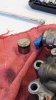
Lets removed the Fuel Pump Housing now, there are four (4) 10mm bolts holding it in place. Be sure to place some rags under the housing as there is oil in it:
This one:
View attachment 11122
These two:
View attachment 11123
And one more located on the back side of the three I have indicated (don’t know where the picture went )
Go ahead and grab an 8mm socket and pull your VC off and set aside for a cleaning later.
Grab your CAP and that 21mm wrench, place the wrench on the "NUT" looking part of the intake cam. Place the CAP into the grooves of the cams on the driver side of the car, if the CAP doesn’t slide in right away, the push or pull the cam in whatever direction needed to get the CAP in place.
BACK TO THE PASSENGER SIDE OF THE CAR!
DISCLOSURE
Grab your jack and block of wood, wrap the wood in a few rags and place the jack directly under the oil pan where the big hole is. And Jack up till it starts to hold the wood in place like this:
View attachment 11124
Grab a 10mm socket and a flat head and remove the power steering and coolant reservoirs. Push the coolant tank towards the emblem on the bumper, it should sit in there just nice, then pull the power steering tank in the same direction and zip tie it down.
Now, grab your 1/2" breaker bar with an extension and a 17mm socket. Break the two lower bolts of the passenger side motor mount. Then grab a 10mm and remove the grounding strap (the side bolted to the chassis not the PMM). Jack the motor up just enough to take the weight of the motor off the chassis. Loosen up the lower bolts some more till the bottom of the bolt head is not touching the PMM. Jack up the motor some more till the PMM is completely off the chassis. Removed lower bolts, then removed top two bolts. Pull out PMM and set aside with hardware.
Grab a 12mm socket, and remove the Power steering pump (leaving the lines hooked up) there are two (2) 12mm bolts on top and one on the bottom. Push it up towards the top of the strut tower and find a way to zip tie in place.
Now you’re going to need to remove your Water Pump Pulley (three 10mm bolts) Located directly below the power steering pump. So grab two (2) 10mm wrenches, place them on two bolts that are close together, and pull them together, one of them will break free. Then move around to the next bolt and do the same thing, do this till all of them are off.
Then Remove your Idler Pulley, located just below and to the right of the Alternator (located on the far top left) use a 10mm socket. Remove and set aside.
You should have enough room to work with now (yes that rag on top of the cam is hiding something):
View attachment 11127
Now, look at your Lobes... these things here on your cams:
View attachment 11125
(the egg shaped parts that press onto the tappets/buckets/spring caps) on the cam directly above cylinder 1 (cylinder on the passenger side) do they look like they are facing each other at a 45* angle, while the sides facing each other are parallel to one another as well as perpendicular to the head like this:
View attachment 11126
Oh that rag... I wouldn’t worry about that rag....
Moving on now.
From here we are going to remove the Timing Cover (TC).
There are three Primary bolts on the TC that are a 13mm they are all located on the bulk near the PMM mounting point, these will be the last to be removed and the first to go on during reinstallation. (Keep this is mind)
These Two that I am pointing at DO NOT need to be removed:
View attachment 11128
There are twenty four (24) bolts total that hold the timing cover on, this includes 3 13mm (located at the PMM mounting point) and the 10mm bolt for the idler pulley. there is also one (1) (located on the far bottom right of the picture directly above) that is a 13mm I believe (don’t let the ripple in the TC fool you, there is no pulley that goes there!) and the other 19 bolts are all 8mm, some are longer than others so keep them in order of where they came from.
Once all the 21 bolts are removed you may then remove the 3 13mm bolts from the PMM area. Go ahead and remove your crank bolt (that is finger threaded on remember)
Now grab your flat head screw driver and place it in between the TC and the intake cam bolt and pry while holding the top of the TC and pull it up from the top (You probably could go through the bottom but it’s just easier to go through the top)
View attachment 11130
View attachment 11129
MOVING ON TO CHAIN, TENSIONER, ARMS AND VVT REMOVAL AND INSTALLATION
Now we have the TC Removed it’s time to move on to the more… “INDEPTH” part of this. (It really isn’t that hard though) We are going to remove the chain tentioner located here with two (2) 10mm bolts:
View attachment 11131
This can be done with ease. First loosen both 10mm bolts on the tensioner. Once this is done, and then completely remove the bottom bolt slowly, allowing the tensioner to spin clockwise on the top bolt. Do this slowly as this is spring loaded. Once the tension is completely removed then remove the top bolt and pull the tensioner out. You can place a small tack/paperclip or nail in the locking hole to keep the plunger in place like this (this can also be done while the tensioner is in the car to make for easier removal)
View attachment 11132
Now you are going to remove the chain tension arm. It has one mounting point on the head and is free to move forward and back, it will simply slide off (be sure to pull the chain towards the front of the car to prevent it from getting in the way of removal of the chain tension arm and the guide arm) So remove and inspect the arm:
View attachment 11134
Both my arms are brand new so there is minimal to no wear on them. If they are chunked I would replace them, but if they have small grooves in them that don’t look deep they should be fine to keep in place. If replacement is needed replace the right one now two (2)8mm bolts hold off on the tension arm. That will come later.
View attachment 11133
On the crank you have the two friction washers and the timing chain gear (keep in mind this order in which they are removed washer/gear/washer)
View attachment 11135
NOTE: when installing the new washers. DO NOT TOUCH THE FACE OF THEM!!! Hold them like this while handling them.
Go ahead and replace the one closest to the block now, and set the gear aside for the moment.
View attachment 11136
Grab your marker, and mark on the VVT and Cam cap where the VVT sits in relation to the cam like this:
View attachment 11137
View attachment 11138
This will allow you to place the new VVT in the proper position for ease of install. Be sure to transfer the markings on the old VVT onto the new VVT. DO THIS NOW!
DISCLOSURE
Now we can remove the chain and grab a ratchet with a 14mm socket and a 24mm wrench to hold the cam in place: This picture is only for reference of where the wrench should go on the cam as I did not take pictures of the removal and installation of the actually VVT itself:
View attachment 11139
DISCLOSURE
NOTE: BE SURE TO REMOVE THE CAM ALIGNMENT TOOL WHEN BREAKING AND TORQUEING THE BOLT!!!!
If you do not, you will damage the timing tool and we don’t want that now do we… Moving on:
Now again, I do not have pictures of the actual removal and installation of the VVT actuator. You will place the 24mm wrench on the cam to hold in place (after removing the alignment tool of course! Be sure to keep the cam in the position it is in otherwise you may nick a valve.) Then grab the ratchet and break the VVT bolt free. Remove and replace with new. Align up your markings and Torque to50.9-55.3 ft-lb. Reinstall your Cam alignment tool now.
Grab your crank Gear for the chain and set into the bottom of the chain like this and slide the gear onto the crank (keeping it taught so the chain doesn’t separate from the gear) like this:
View attachment 11141
View attachment 11142
With tension on the bottom crank gear, put the chain onto the VVT first, then onto the exhaust gear leaving some slack in the middle of the two gears. While using your 24mm wrench you will push the intake cam towards the exhaust cam just enough to pull the chain over the exhaust cam a tooth or two (pending on how loose you left the chain)like this:
First picture is of the loose chain, second and third is tight chain
View attachment 11139
View attachment 11143
View attachment 11144
Now we can reinstall your chain tension arm (the one on the exhaust side as the other should still be in place)
View attachment 11145
For the installation of the new tensioner, it will be the opposite of removal. (Keep in mind, the new tensioner has a locking pin in place to keep the plunger compressed, DO NOT REMOVE THIS YET) So install the top bolt first:
View attachment 11146
Spin the tensioner in place and align up your bottom bolt hole and tighten both. Then press the tension arm into the tensioner and slowly release the locking pin to free the plunger and lever.
View attachment 11147
PUTTING IT ALL BACK TOGETHER
DISCLOSURE
From here it’s all backwards for re- installation. First be sure to apply plenty of sealant to your TC along these areas anywhere else is unnecessary:
View attachment 11149
Install and align up your VC and install these three bolts first, make them snug but be sure the TC can still move slightly:
View attachment 11148
Install the rest of the bolts and tighten all in accordance with the FSM.
NOTE: BE SURE THE TOP MACHINED SURFACE OF THE VC IS LEVEL WITH THE TOP MACHINED SURFACE OF THE HEAD; IF THIS IS NOT LEVEL/FLUSH WITH ONE ANOTHER YOU WILL HAVE A LEAKY VALVE COVER!
TIMING THE MOTOR
DISCLOSURE
Once you get the VC in and on and tightened up, slide on your second friction washer onto the crank. Now oil up the inside of the crank pulley for ease of installation, slide the pulley onto the crank and install your M6x1.0 bolt into the hole on the pulley. Once this is done install the crank bolt until snug, have someone get in the car, press the brake all the way to the floor and hold, then place the car in 6th gear to prevent the crank from spinning. You will then torque the crank bolt in two steps
First torque to 70.9-76.7 ft-lbthen let the bolt sit and cool for a few moments
Second is the 90* turn so.
Now you will grab your marker and draw a line on the bolt and the pulley to show where you’re starting point is (this is probably the hardest part of this entire install)
View attachment 11150
Now whilst holding the brake and the car in 6th gearyou will spin the bolt with a breaker bar as far as you can before it feels like it’s going to stop. Then let it sit and cool down for a moment the bolt should be around 45* from the marking on the pulley. After it has been a few moments repeat again until you have the bolt turned a full 90* from the original mark you made.
View attachment 11151
From here, you just go backwards. Re-install your crank sensor, remove your pulley bolt, remove TDCP, remove Cam alignment tool. The hard part is now over so put the car back together.
NOTE: be sure to add oil over the top of the chain and cams before putting the VC back on. Be sure to prime your fuel pump, and DO NOT FORGET THIS:
View attachment 11114
Take your time do your research and be sure you have EVERYTHING YOU NEED!!!
IF YOU HAVE ANY QUESTIONS, PLEASE, ASK AWAY!!!
If you have noticed anything missing or something that should be edited please post away.
Roku

Can you elaborate a bit on what can happen if the tensioner isn't clicked out that extra one or two slots? Just curious
The entire point of doing that is to ensure there is plenty of tension on the entire timing set before you torque everything down.
In regards to the section titled "Setting the chain tension".
- With the crank pulley off, pull the pin on the chain tensioner. Now PUSH the left chain guide (by the tensioner) in toward the chain. It should click out another notch or 2. This is very important as if you forget this and the tensioner clicks out AFTER you've tightened the cams down, your tension will become uneven and you'll need to loosen both cams again and start over. Ask me how I know.
- Cycle the chain through a couple cycles by spinning the VVT. Remember, the crank is locked by the TDC pin and the cams are locked by the alignment plate so the 3 sprockets & chain are spinning freely.
- Tighten the exhaust sprocket first while holding the cam with a 24mm wrench. The sprocket should NOT rotate relative to the cam when you torque it down. If it does, your chain tension will become uneven.
- Now torque the VVT. The same ^^ goes for this sprocket.
Awafrican
Moderator
Yeah, but you can touch it with clean hands, cover it in engine oil and slide it inIs this the cam follower? I'm having a hard time getting it back into the cam housing without touching it too much.
djmano
Greenie Member
Thanks again for all the help especially to the OP.
In this thread: https://mazdaspeeds.org/index.php?threads/timing-the-mzr-disi.8722/
He mentions removing the camshafts first when finding TDC as to not damage a valve. I don't believe that applies to the standard method of finding TDC with the TDC pin inserted into the block when the engine is still in the car like for this write-up but I just want to make sure before I do this step.
djmano
Greenie Member
So I shouldn't have the camshaft alignment plate (CAP) in when removing the crank pulley bolt, correct? I'm seeing conflicting advice on this step.
I'm guessing having the M6x1 bolt threaded through will keep the crank at TDC? (planning to use impact to take off bolt). Thanks again so much.
I'm guessing having the M6x1 bolt threaded through will keep the crank at TDC? (planning to use impact to take off bolt). Thanks again so much.
So I shouldn't have the camshaft alignment plate (CAP) in when removing the crank pulley bolt, correct? I'm seeing conflicting advice on this step.
I'm guessing having the M6x1 bolt threaded through will keep the crank at TDC? (planning to use impact to take off bolt). Thanks again so much.
It can be confusing, and it's literally been like 10 years since I did this initial write up. But, I'm always open to help out. If you'd like, PM me and I'll give you my number to call and I can walk you through and answer any questions.
Sometimes getting someone on the phone is much better than reading it.
However, when removing everything. The big thing/only thing is to have the TDC pin in place on the crank. Don't worry about the cams until you are ready to line everything back up and start to actually set timing and torque everything down. As long as the cams are generally in the correct position (TDC cylinder 1) when you put the pin in, you should be fine. The crank will move freely after timing is broken same with the cams.
The M6 bolt is only there to help keep the pulley in alignment with the crank. There are a couple tools that help with this as well.
I might need to go back through and redo this write up to make it even easier to understand.
I hope this helps.
Similar threads
- 0.00 star(s)
- Replies
- 1
- Views
- 44
- 5.00 star(s)
- Replies
- 6
- Views
- 478
- 5.00 star(s)
- Replies
- 1
- Views
- 249
- Replies
- 4
- Views
- 234