Mazda CX-7 Project

If you mean alcantara with already adhesive layer it is not real alcantara or if it is premade it would be expensive as hell and hard to stick. The only way is to get raw material and buy adhesive spray cans specially made for connecting materials. If you want headliner buy 3 cans , for whole interior 6 cans (400ml per can) is recommended.

So: I recommend adhesive spray+ raw alcantara
 
hey, quick question, do you know if the brembo m85 brake pump will fit mazdaspeed 3 BL? cant find any information if cx7 has the same brake pump as msp3. also the brake calipers were p&p? whats the mounting? i have alfa 159 front brakes and im thinking about rear calipers, but after brake pump... if msp3 has the same mounting xD
 
Unfortunately i have none knowledge about ms3 but i think as long as the servo mounting threads will allign with ms3 you can swap the whole assembly - servo with M85 Pump along with spacer for leak proof working, for pretty cheap comparing to direct fit sets.
Onto the mounting points.
No , they are never the same except you are veeeery lucky or have dedicated adapters.
I still didn't close the brakes update, as i mentioned, i need to order CNC'ed adapter plates for rear and adapter for wider mounts for the front. Now i don't have the photos showing how wider they are but you can , all of you guys can be sure when I'll find time soon , using my friend 3d scanner I'll design and ordered everything you need for CX7 18Z swap and show you everything, including schematics - the most useful but rare to find on the internet things. When i want to design some custom parts always i search for schematics, but usually there aren't any or they are too simplified or are paid /don't exist so i need to grab my measuring tools , dismantle whole car and the i can get what needed .
 
NEW INTERIOR MOD UPDATE
PART IV - LAST
I finally managed to one piece finish these hard Y covers for A pillars . I also did some finishing touches to the headliner and other pillar covers so the whole interior is ready to install - I'll give it time to harden adhesive. Tomorrow I'll put back together everything and next post as promised will be comparison from rally interior with stock interior. Also as mentioned only thing that's going to change is Sparco seats and harness, a nitrous bottle and extinguisher system.
As always photos.
IMG_20250918_201237.jpg IMG_20250918_202846.jpg
 
Great! Thank you for the info. Also, i see you're from Poland, so will probably try to text you in private ;)

Edit

I see there is no option for private, nevermind
 
Replying: Unfortunately there is no private message option

THE LAST INTERIOR MOD UPDATE
PART IV - COMPARISON

SO THE STOCK INTERIOR - photo from web
IMG_20250907_225711.jpg
And mine customed INTERIOR for now looks like this - as mentioned other Sparco updates later and I'll make these vents pieces black
IMG_20250919_113452.jpg
IMG_20250919_113512.jpg
Excuse me that the car is dirty AF but today is detailing day .
Also i want to alcantara the Gauges pice under the windshield but I'm planning vacations so I'll be stopped for some time
Stay tuned
 
HELP WANTED on RPM SHIFT LIGHT

As mentioned I'm still working to get the universal adjustable rpm shift light working in my diesel truck.
As we found out, Cluster gauge doesn't have clear signal or any signal that even converted could work.
We also found out ecu is not a good signal source too - there isn't something as direct point to connect or there aren't any clear ecu pins schematics to work out ath new .
The last though i found out is that some diesel trucks (older) had dedicated W signal output from alternator that mostly took role of rpm teller.
Unfortunately most new (2010 and +) models does not have it.

So my question to anyone having same issue is:

Should i dismantle the alternator and with my knowledge take out this W connection?
Or buy some rmp scan module with laser detection on the alternator or belt and adjust timing ect ?
Or you can suggest sth?

Waiting for every idea.
Note that programming is not my strong side and i only do car mechanics and industrial 3 phase engines. Tuning as a side job and Electric Motors as a main job with degree.

If possible reply quickly because when I'm back from vacation I'll be renewing my tuning run.
Also for admin, could you make only this post as a new thread ,, Electrical Wiring,, on my profile to further discuss some more advanced car wiring etc?
 
NEW UPDATE
Probably you've all scrolled on the internet if you knew what you needed but there's wasn't any ready kit , only expensive gr Yaris dedicated one.
An I'm talking about water cooling.
From theory it is a system thet automatically or manually steered sprays a foam of cooled water directly onto intercooler to cool down air quicker meaning you get stable horsepower and better throttle response.
In practice you have a can or more adequately reservoir with a 12V fluid pump that pumps fluids like water when triggered. Then the fluid travels through set of hoses an then it's turned into mist by little taps.
I myself was scrolling through web wondering how this simple system can cost me potentially 2000$ if bought one for Yaris and still needs to adapt it in some way.
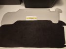
I decided to change that an for you... Mazda Enthusiasts i present to you this.
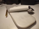
Easy , money saving system that doesn't drip fluid and hase a capacity of 1,5 liters which may not be enough but it's enough for one lap or quick drag run.
IMG_20251002_101540.jpg
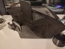
You may be wondering what's that. And I'm happy to answer. That is simple washer fluid reservoir with a 12v fluis pump attached to it.
Another question is why i have 3 of these?.
1. Because that big reservoir with pump was cheaper (around 25$) and it wasn't available in big stock so i bought everything they had ;)
All you can see is already premoded setup because just shoving stock can is not enough because it meets common problem which is gravity - fluids runs on it's own emptying the tank and not when you need it so i added a one way spring pressure valve on the exit which stops fluid from leaking but when pump is running it has enough force to open the valve.
I didn't answer so why I have 3 of these really?

I decided to design best setup and achieve:
1. Better traction
2. Weight reduction
3. Cooling.

And how ?
Remember those drag racing and some guys pouring thick compound on road on tires that is cola like?
That's how.

First system is for traction containing traction fluid such as ,,Black Label,, from USA.
Second is for windshield wipers instead of this big container weighting at least over 3 kilos and more with fluid exchanged with my lightweight setup will save me mass and make more room for turbos.
And third as described is for water cooling.

IMG_20251002_101105.jpgIMG_20251002_101220.jpgIMG_20251002_101303.jpg
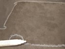
This is simple setup with many sprayers and connectors also with physical trigger so i personally can adjust flow.
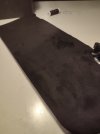
But you know i love professional parts so I can't let use attached to set cheap transparent thin hose so instead I'll be using 5mm FMIC High Performance Vacuum hose which can withstand impressive conditions and works well with cold or hot fluids.
IMG_20251002_101517.jpg
That is it. I still need to wait with traction and cooling system to install due to under restoration combined with stage 3 under tuning which are poliuretane bushings, rust proof suspension, Brembo brakes and much much more .
Soon I'll only show you a washer fluid swap and we'll compare how much of ,,swimming,, weight we dropped making car more stable in high speed cornering.
As always stay tuned for future updates.
 
NEW UPDATE
12V TRACTION COMPOUND SYSTEM
WATER COOLING SYSTEM
WASHER FLUID SWAP

I did some calculation and all you need is:

3x T-connections 5mm
1x One way spring valve
9x +2 (valve) T-clamps less than 10mm
12V Pump reservoir
+/- Cabbles length depends on mounting
6 meters of 5mm FMIC Vacuum Hose
4x Adjustable mist sprayers


For water cooling you'll need


1x 12V reservoir
6metres of FMIC 5mm Vacuum hose
4 or 6 T connection (for 4 or 6 sprayers)
15 x or 21x T-clamps (for 4 or 6 sprayers)
4x or 6x sprayers
1x One way spring valve

For Washer fluid swap you'll only need

1x Tank
1x One way spring valve for safety or no valve (depends on preferences)
3x T-clamps
1meter of 5mm FMIC hose (optionally- around 10cm for valve , can be no hose if just swap without valve or 1m or more if tank relocation in engine bay)
 
Last edited:
NEW INTERIOR UPDATE

Last detail i didn't have time for i started to sew with alcantara - Sunvisors
Earlier i bought another CX-7 visor that were listed as black so i thought i had ready plug&play but they came dark grey so i teared the material, dismantled all elements, painted elements black.
Only difference i spotted is my sunvisors are with build in mirror lights and these ordered are non lighted. Even better because every non used electrical accessory will give me opportunity to mount it out and in the future swap smaller Lithium lightweight accu.
As always photo and stay tuned for future updates
IMG_20251002_124639.jpg
 
NEW INTERIOR MOD UPDATE
FINISHING DETAILS

I managed to do one of the sunvisors and man these are as hard as those Y- pillars.
Anyway the best way to do it is:

Precisely with surgical precision cut even every seam seal on oem sunvisor
IMG_20251002_194920.jpgIMG_20251002_194155.jpg
Then take alcantara and lay down back of the oem material and cut exact pice
IMG_20251002_192509.jpg
If you did wrong side as here because you can see it's not mirror view redo one piece. That's why i didn't recommended ordering alcantara down to last mm needed. Always have some backup.
Redo
IMG_20251002_193852.jpg
And you should achieve something like this
Then there's the trickiest part which is how to apply it onto sunvisor's ,, chassis ,, the smooth way.
simply lay down both materials as ,,flat,, sunvisor,, where the material side should ,,hide,, inside. Why? Because we'll gonna sew the edges making ,,pillow,, like bag that we'll going to glue onto visor.
IMG_20251002_200844.jpg
Then you should have it like this.
IMG_20251002_211228.jpg

Now the part that should explain to you why we hid the final material inside. Flip material from inside out.
Now put adhesive onto visor and stretch the material.
Remember you need to do it one try so don't hesitate practicing in stretching everything perfectly.
At the end you're done , just apply parts and fix connections you broke or lines you forgot to sew.
IMG_20251002_212552.jpg
I'll finish this one with rest of the parts and tomorrow i hope I'll put them back into car.
Stay tuned
 

Attachments

  • IMG_20251002_212516.jpg
    IMG_20251002_212516.jpg
    1.3 MB · Views: 1
  • IMG_20251002_211821.jpg
    IMG_20251002_211821.jpg
    1.2 MB · Views: 1
  • IMG_20251002_194926.jpg
    IMG_20251002_194926.jpg
    820.7 KB · Views: 0
  • IMG_20251002_193258.jpg
    IMG_20251002_193258.jpg
    1.6 MB · Views: 1
  • IMG_20251002_191815.jpg
    IMG_20251002_191815.jpg
    1.1 MB · Views: 1
NEW INTERIOR MOD UPDATE
I finished those sunvisor and i added this little detail as a strap for any documents as in oem but smaller.c95f7f76-7b33-45e3-a6f2-5c0cc9bbd515.jpg
 
NEW INTERIOR MOD UPDATE
Finally done . Sunvisor are good but not as perfect as i wanted them to be bot here you have, full suede.
IMG_20251003_213403.jpg
 
NEW RPM SHIFT LIGHT UPDATE

I found best solution for non working rpm shift light that may save any build.
Mainly those drag racing look shift light rely on simple pulse signal generated by a car computer or by a sensor detecting movement with calculated ratio of spins per some time that gives you rpm. RPM - Rotations per minute .
What my idea does is it relies on magnetic field generated by an alternator and calculates it giving your rmp light readings.
There is no need for searching diagram or check every wire as i did. I actually ordered the last one available .You just simply buy an Rpm adapter like shown below .
IMG_20251004_225212.jpg
The only thing it's needed is calibration so take your time. Also a good mounting. Remember alternator as engine is moving parts so recommend zip ties won't work for me. When I'll get to installation I'll show some of the best and elegant mounting and also make it non visible.
 
Last edited:
LAST ALCANTARA UPDATE (I THINK)

I just finished and installed the gauge panel above the steering wheel. The bending wast hard to straighten but i found a way.
As always quick shot and stay tuned IMG_20251007_202935.jpg
 
MAINTENANCE UPDATE - HOW TO CLEAN YOUR OIL CATCH CAN/TANK

Firstly remove the hoses itself and whole can from the chassis however you installed it- mine is screwed on the left side
IMG_20251010_190157.jpg
Then look if your can is empty - look at the transparent hose
IMG_20251010_190219.jpg
Mine after a year or sth was pretty full of oil mist and water from the valve cover.
So let's unscrew the drain bolt on the bottom
IMG_20251010_190359.jpg
IMG_20251010_191528.jpg
It's recommended to disassemble whole can completely and clean all the parts
IMG_20251010_192458.jpg
IMG_20251010_193046.jpg

Lastly reassemble everything
 
RPM SIGNAL / SHIFT LIGHT UPDATE

I did this rpm adapter the better way as promised - no zip ties were used to attach sensor.
Let's start with preparation step. Remove engine cover and locate alternator - either driver or passenger side- usually on the left.
Look for the best position for the sensor - as flat as possible and as center to the core as possible IMG_20251019_111714.jpg
Qnd after positioning
IMG_20251019_111801.jpg
It sits nicely flat.
Now the trickiest part is to design mounting point so it won't fall of and damage anything especially if it would fall onto the belt and get under it causing it to slip or cut it. Now I'll skip it and move onto wire mounting.
Usually there are two options to run wires, ether run them alongside some stock wiring or follow some fuel lines and other solid points .
BE AWARE that fuel lines especially tend to get hot , around 100 degrees Celsius so prevention is key to not set up car on fire .
Heat insulation tubing works perfectly, it's capable of withstanding up to 600 degrees Celsius and it's elastic. It isolates heat totally so don't worry about wrapping it with some tape or as for me the material oem style tape for estheticsIMG_20251020_173257.jpg
And wrapped in black material tape
IMG_20251020_174625.jpg
The trickiest part is to design some stuff to hold sensor. I designed a hold that's tighten by upper bolt just on alternator so it's easily available. Worse is to estheticly form this adapter from 2mm steel piece not to scratch it or bend it too much.
Unfortunately only pic i have is the prototype on paper with dimensions and optional angle.
IMG_20251022_165901.jpg
It should look like this
IMG_20251021_204003.jpg
And after bending it's optional but i oxidized the whole piece, then degreased and painted it with two layers of black matt paint and one thin layer of anti-gravel (Coating used on off road and rally cars that prevents rocks from making scratches)

Next step is cosmetics.
We need to sand down a little bit of unnecessary ,, material,, .
Wrap as much as you can the area to prevent shavings to fall into alternator and causing shortouts and a lot of electrical damage and risk of fire.
IMG_20251022_193814.jpg
That is a little mushrooms you'll recognize easily. REMEMBER, IT IS FOR CX-7 ONLY, In other manufacturer ALTERNATORS MAY BE DIFFERENT AND A MUSHROOM COULD BE A PART OF CAST, SANDING IT MAY CREATE VISIBLE HOLE AND A RISK OF MALFUNCTION DUE TO WATER ECT GETTING INSIDE.
Here is not so we can gently grind area then smoothening it with scotch and applying anti rust coat for great look.
IMG_20251022_194741.jpg
And if we're done we can assemble everything.
IMG_20251022_203240.jpg
It will look like this, I personally think this look much better than zip ties aor even some clamp. I tried to put a 140-148mm vband but even when managed to squeeze it onto alternator, the intake manifold is too close at the back blocking band to slide correctly.

I still need to calibrate this sensor because it won't magically adjust itself. I didn't read or understood the manual and turned on the engine without putting device in calibration mode so the light isn't on. Maybe it was when turned on for a short while but i couldn't see it from inside. I'll calibrate it anyway and if there will be other issues like poor ground point I'll correct it and update it here so you would know what to look for while installing.
 

Attachments

  • IMG_20251022_195139.jpg
    IMG_20251022_195139.jpg
    1.4 MB · Views: 1
RPM SHIT LIGHT AND ALTERNATOR SENSOR
FINAL UPDATE

finally my shift light works and it's set to 4k rpm .
I'll be quick, few corrections needed to be done.
First this sensor does not accept hot wire 12v, it needs to be the ignition on 12v that only works after turning key in acc position.
I made this little fella for connecting it onto hks existing acc wire .
IMG_20251023_195426.jpg
Then calibration time.
Fuse the calibration circuit - white and one of black wires together.
Then run the engine for a while, accelerate to exactly 1k rpm and disconnected these wires , led light will start flashing, after 10 seconds fuse them back together and you have working gauge. But....
The calculation ratio is 1:2 so for every 1k rpm you need to set shit light for 2k rpm so when i want 4k rpm i need to set shift light to 8k rpm and everything works perfectly.
Stay tuned for future updates
 
NEW UPDATE - 1 YEAR ANNIVERSARY OF THE BUILD
As one year passed since first seriously mods rather than putting some stickers (which were removed later in my Anti-Lame mod)
On the video below we can see how different the car became so far, better engine sound (intake) better interior (alcantara and blacked elements along with red led elements.
View attachment VID_20251024_181456.mp4
Stay tuned for further mods and maybe on 2'nd anniversary this car I'll become much more advanced and twice as powerful as it is now which was the mission from the start.
 
Back
Top