Mazda CX-7 Project

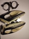
NEW UPDATE - DETAILING PART I- GLASS

I decided ti give car a good clean , it was not in bad condition but paint is slightly scratched and all glass surfaces are strangly matted (maybe from paint dust from painting the bottom). This dust is hard to remove but there are two ways . Use special polishing compound like 3M or special oxide dust to polish the surface or use polishing paste for headlights. Put the compound in preferred way, directly on glass or onto the pad. Spread the compound and usung medium force start polishing the whole surface. Then switch to harder pad and using less force but faster speed polish again. Lastly use polishing cloth pad (furry one ) finish surface. Grab microfiber towel and remove excessive dust and pase from surroundings. Last step is to ceramic coat surface to prevent such dust from ruining glass (but surely don't paint near car or cover everything including car if need to paint nearby.
KEEP IN MIND that best results are achieved after a great wash which in my case was
1. APC strong 1:5 and clean every corner using detailing brush
2. Rinse
3. Active foam to de-acid paint
4. Use special sponge or washing glove to clean everything
5. Pressure washing
6. Clay bar whole paint
7. Drying using firstly, special blower to remove water from gaps and secondly drying towels.
Let the car dry for a while

That was day one

Today i spent whole day polishing headlights, mirrors , taillights and glass.
Then ceramic coated them.
In next part I'll do paint polishing in three stages , coat rims , and protect tires with tire gel .
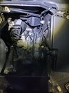
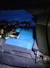
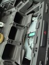
I cleaned whole interior in every possible way wich mainly took whole day .
As a result car is brand new on the inside.

Every spot was cleaned including door insides , gas cap.
Removing some elements was needed such as seats and rear couch.
IMG_20251101_150510.jpgIMG_20251101_135204.jpgIMG_20251102_132801.jpgIMG_20251102_160022.jpgIMG_20251102_162539.jpgIMG_20251102_181534.jpg

Part II - paint correction soon.
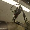
 
NEW UPDATE - DETAILING, PAINT - PART II - LAST

IT'S last part of detailing my mazda because i realized it's a waste of time . Not in a bad way but trying to make 15yr old car look brand new in some states is not reasonable. I realized the trueness of the phrase
,,old cars don't try to hide imperfections, they wear them with pride,,
I also ran out of ceramic coat and only doors are not costed. I will make this car full carbon in the future so it's not necessary to cover them and i think i did a great job.
Here is the final result.
IMG_20251106_185603.jpg
IMG_20251108_063522.jpgIMG_20251108_063407.jpg
Stay tuned for future updates
 
Last edited:
PROJECT MAIN UPDATE

I can proudly announce i started to create custom Pandem bodykit for my CX in drag racing style because it ll be a drag build.
Phase I included prototype sketches - done

Phase II corrections to sketches, aerodynamic simulations and various tests to achieve perfection.

Phase III Ready 3D model from scans and ready ti print on elements which will be printed then taken to make negative copy.

Phase IV Creating final parts - full carbon chassis (covered) and full carbon made parts from moulds.
 
NEW QUICK UPDATE - ADDON TO CERAMIC COATING

That's how a nice seal from rtv should be done on the shark fin antenna, not as i did as a noob earlier.
I personally think that it can't be than better and my skills in tuning/detailing are growing quick while doing this project
IMG_20251120_175133.jpg
 
New Year Update
It started ,,fabulous,,
IMG_20260103_135514.jpg
New Racing Sparco gloves
Snowy weather aaaand?
And a tree
IMG_20260103_203501.jpg
Couldn't imagine ,,better new year,,
Now my bodywork skills have finally been challanged. I only need to order new/used in good shaped trim, swap halogen unit (restore black out mod) , weld plastics and smoothen. And finally paint bumper. Then i can proceed with my secret project to be released after success.
 
Dang man. That suxks! I have RaiderFab if the bumper won't stay flush.
I'll do my best and it will be as OEM, trust the skill
The OEM bumper won't be needed strictly anymore but why I'll announce here after I'll be sure one step of my secret project will succeed
 
,,New Year,, Fix - Update
I managed to fully inspect damage, small issues I fixed on spot but those unfixable as plastic trims i dismantled and took home for repairs. Whole Xenon trim (without lamp, including only trim) needed to ordered , i need car soon and i will fix it with ease later.
After part arrival i prepared my tools , dismantled everything and washed parts
image-1768332540830.jpg
after washing them with apc ,brush and rinsing with water i let it dry and moved onto repairing broken clip on ordered part.
After welding and sanding spot that turned out durable i repeated washing proces.
Then i took the chrome trims for sanding. On the new one it was easy but older one was dechromed with plasti-dip so removing it took some time
IMG_20260115_201943.jpg
At least it came off easily because it had a skin like texture.

Before sanding IMG_20260115_201504.jpg
And after sanding
IMG_20260115_201530.jpg
Now , after drying and decontamination process i took my base coat and painted preped trims with 2k base coat
IMG_20260115_204337.jpgIMG_20260115_204320.jpg
I love my base coat which i only used because i always achieve smooth even surface that doesn't need to be modeled and sanded that much.
After 2 layers i used my matt black paint and layed 4 layers of it which turned out great.
IMG_20260115_222352.jpgIMG_20260115_222433.jpgIMG_20260115_222444.jpg
I let it dry at least 24 hours in dry atmosphere of 24° with 30% humidity as always.
Then i checked everything once more and after making sure coat it durable i assembled everything.IMG_20260116_123614.jpg
That i think is much more better trim than oem silver one - permanently dechromed and nice looking
Only things I will change in future is when I'll set up my galvanizing setup I'll mahe rust proof bolts on this trim and every other because these rusted bolts do not fit this beautiful black trim.
Last step is to assemble whole car to its mint state, polish headlights and daylights in this trim and repair crack on the bumper which i think I'll include here as an update post.
Stay tuned because nice things will be coming soon i hope
 

Attachments

  • IMG_20260115_201334.jpg
    IMG_20260115_201334.jpg
    1,016.2 KB · Views: 2
New Update - Calculations on Brake System

I tuned my brake setup as described much earlier - new stronger Brembo M85 054 brake pump thet fits perfectly - only needed to machine adapter. Brembo 18Z 6 pot Calipers on front and 2x 4pot on rear - one pair as normal brake and other as hydraulic ebrake. That setup is confirmed. I only need to purchase steel lines and ebrake pump , make my own ebrake lines and steel lines (flexible).
Assembly updated will be made if i will successfully make my two surprise updates related to suspension and brakes. For now without these updates I can't proceed with assembly.

Today's update is about what would happen if you only swap calipers instead of taking care of the whole system (pumps lines etc.)
I took dimensions of OEM Mazda CX-7 FL Calipers and compared them to Brembo 18Z System. Then i took the data to calculate both systems capacity, and power efficiency with bot OEM (Bosh) brake pump and Brembo (M85 054) pump. What i calculated should be warning to everyone that prefes look over functionality.

Not to bore everyone I'll present only basic calculations. Let's begin


OEM
Front Caliper , 2 pistons , 45mm each
Rear Calipers, one piston, 45mm
Bosh pump disarmer (piston) 22mm

Brembo
Front caliper , 2 × 30 mm, 2 × 34 mm, 2 × 38 mm
Rear caliper , 2 × 28 mm, 2 × 30 mm
Brembo M85-054 (piston) 25.4 mm (1")


Piston area calculation:

OEM
Front caliper - 3 182 mm² ( 2x π x r² - 2*3,14*22,5²)
Rear caliper - half of it so - 1 591 mm²

Brembo
Front caliper
2 × 30 mm → 1,414 mm²
2 × 34 mm → 1,814 mm²
2 × 38 mm → 2,268 mm²
Total: 5 496 mm²
Rear caliper
2 × 28 mm → 1,232 mm²
2 × 30 mm → 1,414 mm²
Total : 2 646 mm²

Total area - 16 284 mm²


Master cylinder area (with brake pump)

OEM - 380mm²
Brembo - 507mm²

Required fluid volume for pistons

0,30mm - piston movement

OEM
9,546 × 0.30 = 2,864 mm³
Brembo
16,284 × 0.30 = 4,885 mm³

Effective safe piston stroke: ~15 mm

Available Volume for master cylinder
OEM 22 mm
380 × 15 = 5,700 mm³
Brembo 25.4 mm
507 × 15 = 7,605 mm³

Reserve = how much volume remains after meeting system demand, so

Reserve = (Vmax-Vrequired)/(Vrequired)
OEM system (OEM Master C)
+99% reserve
Brembo system (OEM Master C)
−14% (INSUFFICIENT)
Brembo system (25.4 mm Master C)
+52% reserve

Results speak for itself i think, oem master cylinder with Brembo system will probably k*** you on emergency braking.

Stay updated
 
New Update - Long
Glovebox hidden Gauges/ Dechroming

Today i installed AFR (Air Fuel Ratio, Water Temperature and Exhaust Temperature)

*One mistake was made but I'll instruct you not to make it*
And the mistake was i wanted glovebox gauges so i wanted to drill 3x 51 mm holes to fit gauges. One main problem is i tried to take off the front panel but... it's welded so it's veeery hard to repair it because you can't use any glue because tension will pull it apart.
I just rewelded it with glue for plastic for extra strength
IMG_20260314_162445.jpg
I also supported it with iso tape while it cooled down.
Back to the update - glovebox panel is not a good spot - it only fits 2 on the right because of the closing mechanism - reference photo
IMG-20260314-WA0004.jpeg
You can ofc try on your own to have 3 but in my opinion not worth having non functional glovebox.
I made something even better.
But before yo make anything with wiring or trimming element MAKE SURE YOU ARE ABLE TO MAKE WIRING PASSAGE THROUGH FIREWALL INTO ENGINE BAY (SAFELY)
For myself i used 16mm drill with latche made thread that can be connected on threaded extension. That setup enabled me to drill that hard to reach hole (i showed it with battery relocation).
IMG_20260314_180443.jpg
All is perfectly straight after tightening and have no play at high speed. Before drilling remove SOME of the insulation and tap it A LITTLE for stability at the beginning of drilling.
AVOID PUTTING PRESSURE AND SECURE THE HOSE SHOWN NEXT TO AVOID PUNCTURING.
Start around here IMG_20260314_183636.jpg
And when you keep drill stable with low speed and force you should exit here
IMG_20260314_183717.jpg
And i blurred the area to help you spot this hole.
I also removed the insulation aside (i will create my own with stage 3 engine bay update) and i used this rubber passage to prevent shortcuts due to wires grinding over engine wall
IMG_20260314_191555.jpg
It's not perfect but temporary (PASSAGE may be stiff as here and not perfectly round because after pushing through it needs some time to shape)
You also need to choose correct size
IMG_20260314_191056.jpg
After doing it you will be able to handle this update.
First trim the glovebox IMG_20260314_171831.jpg
It should not hit any of the gauges while closing so doing measurements every time ya want to cut parts is NECESSARY.
Then pre-position gauges and mark your holes. Take your time - ENSURE your setup is correct because it won't look nice to have miscalculated holes everywhere IMG_20260314_180017.jpg
While drilling i recommend leaving tape - it's guaranteed that holes will be smooth. Also use barely no force and medium/high speed.
It's best if you practice drilling on any other material because the last moment is most important. Keeping force to drill faster is wrong. It will make your drill to fall deep inside and damage existing wiring.
Now handle wiring - accordingly with wiring diagrams provided with gauges.
I won't include it but i recommend sectioning wires - Ignition+12V into one string, another with Vehicle Ground cabbles and another for aignal wires so you won't accidentally pull ground wires into engine bay instead of signal ones.
Always put SHRINK TUBBING FIRST BEFORE SOLDERING ANYTHING.
Correct soldering
IMG_20260314_215905.jpg
Solder is spreaded evenly. Tip is using soldering paste then putting solder so it will suck into wiring instead of making ugly blobs or just staying on the outside
Then you can shrink your tubes
IMG_20260314_215851.jpg
I always put one LONG piece on each wire and One long on all of them.
For now I'll quickly move onto showing you dechroming results IMG_20260315_112606.jpg
I needed to remove some parts to fish through the wiring so i figured out it is perfect to make things look cool- I dismantled chrome pieces , sanded them and painted my favorite matt black 4 layers to ensure durability.
IMG_20260315_153110.jpg
I even removed those tiny knobs. BE CAREFUL WHILE REMOVING THEM NOT TO STRIP ANYTHING that will make them unusable
Here is how they should look after correct removal IMG_20260315_153141.jpg
I also removed bigger vents chrome rings and painted them as usual IMG_20260315_172257.jpg
And results are fabulous IMG_20260315_172737.jpg
IMG_20260315_164332.jpg
Back to gauges
While battery relocation i made +12V , -12V and ground lines hidden in (in my opinion) useful spots for future updates so for today i saved a lot bu just using one of these spots
IMG_20260315_114821.jpg
Signal wires were tightened in engine bay because for now I don't want to connect anything until I'll make stage 3 for engine and stage 2 for suspension rebuild and upgrade.
IMG_20260315_115404.jpg
Then i mounted gauges holders
IMG_20260315_101827.jpg

REMEMBER to cut nice square outlets for connectors to connect into gauges. Those holders ofc have holes but as we put them upside down they lose purpose.
And test fit again for glovebox closing
IMG_20260315_111700.jpg
Everything works perfectly for now from staring animation to lighting and parts fitment (assembly and wire layout)

*At first i plugged +12V ign switch onto red wire but it is wrong- gauges will be working strangely or non working. The correct +12V line is green/yellow one*

I'm electrician so for me red is hotwire green and yellow would be ground:) but i forgot in Turbo timer update I decoded wiring color codes.

Stay tuned for next update.
I'll try to include Video of correct startup and some extra stuff
 

Attachments

  • IMG_20260314_183839.jpg
    IMG_20260314_183839.jpg
    1.2 MB · Views: 3
  • IMG_20260314_194214.jpg
    IMG_20260314_194214.jpg
    1.4 MB · Views: 1
  • IMG_20260315_122210.jpg
    IMG_20260315_122210.jpg
    1.3 MB · Views: 1
New Update
Attachment to latest Gauge/Dechroming Update

Promised Video showing correct startup sequence for gauges . Why i made those 3 in glovebox is i don't want to have Christmas tree on dash. Keeping most important as oil pressure on dash and those ,,dyno,, or ,,track,, use to be able to hide them during daily driving. I stiil can monitor engine life but when on track i simply open glove box and have full data panel. And let's be honest, we car guys usually drive alone so open glovebox won't be a problem.

Video is made in dark because it's late at my location and we can see better how cool gauges look
View attachment VID_20260315_191256.mp4

And extra stuff
I wanted to show you how alcantara handled time (i think half a year? ) Direct sunlight and extreme cold during winter was nothing and it should be like that.
IMG_20260314_151043.jpg
And those patterns are usual for alcantara. Any touch will make this cool pattern.

Stay tuned for future updates.
 
Back
Top