AYOUSTIN
Greenie Member
Okay, so as some know I've been doing some flow testing of parts on a flow bench. Some of these parts are intake manifolds. The main reason why I'm doing this is because it's never really been done before. Flow testing parts is just like dynoing a vehicle. It gives you a good idea on how something is performing but it's fairly hard to accurately compare to results of others. Just like dynos, bench results can differ based on ambient conditions, bench calibrations, accuracy of the device, test pressure, etc. So when a company claims that their part flows xxx CFM it honestly doesn't really say much unless they can give more details, and most of the time they don't.
Before I get to my results I would just like to say, PLEASE do not compare my results to that of what others have posted. I have found little in the ways proper documentation for flow tested pieces and I really don't want this to turn into a, "well ______ said that their part flows xxx though". I don't care what a company has to say about their part, the point of this thread is to give an unbiased opinion, with properly documented results.
I'm going to start by covering some of the basics of the tests that pertain to all of the manifolds tested. The flow bench being used is a SuperFlow SF-600. This bench has a FlowCom computer attached to it which allows for great accuracy and ease of testing. All tests were done at a test pressure of 25" of H2O with a max variation of .3" H2O. The industry standard pressure for flow testing in the performance industry is 28" H2O. I chose to use 25" H2O because that is the pressure that the bench is calibrated for. I could have tested at 28" H2O but I decided I would rather have the most precise numbers I could get. The only real difference between 25" H2O and 28" H2O is that the test results would be a bit higher if the tests were done at 28" H2O. All results are in Cubic Feet per Minute (CFM).
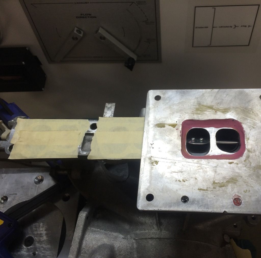
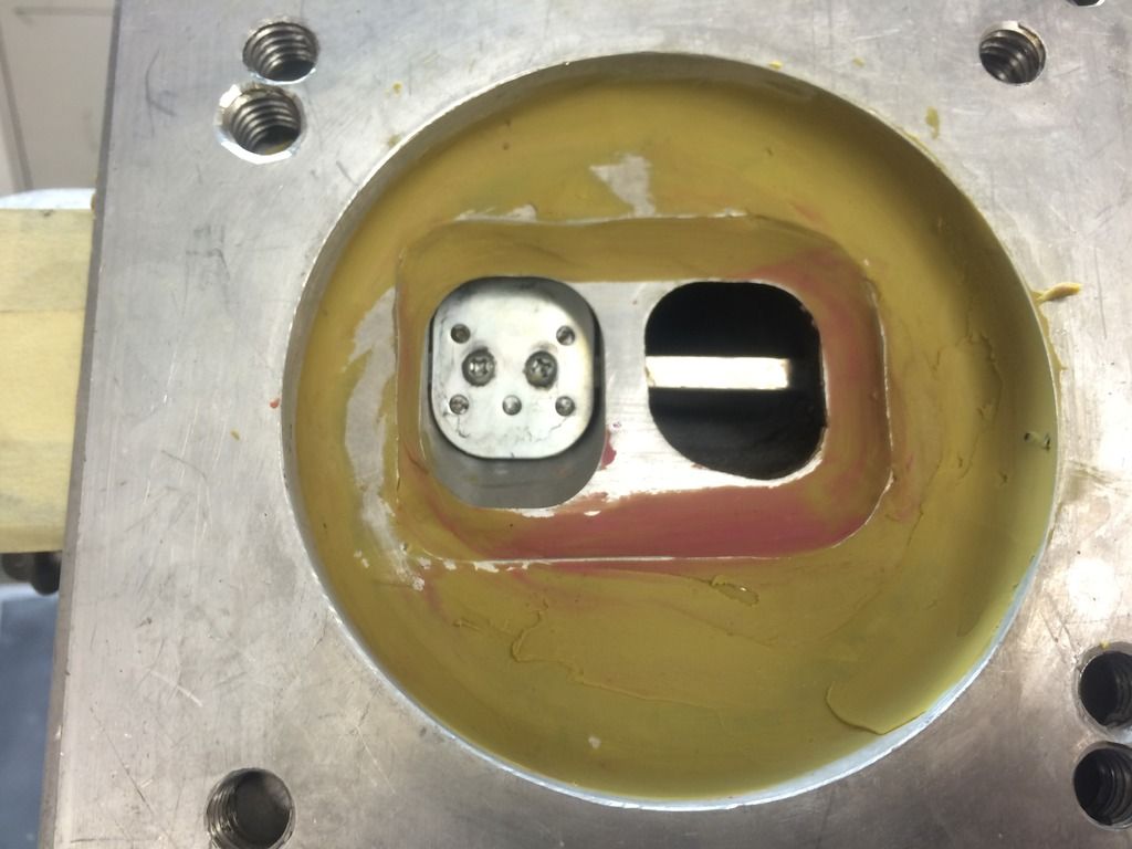
To set a baseline I started with a totally stock intake manifold. The manifold was sealed with modeling clay to an adapter plate and sealed to the bench with clamps and a rubber gasket. I can't say for sure there weren't any leaks but if there were, it was less than a couple of CFM (aka mostly negligible). The VTCS was left intact and tests were done with the flappers open as well as closed. All ports not being tested were covered in tape so all air would be pulled through the throttle body opening. Lastly, every port was given a small exiting radius made of clay. This was done to help seal as well to keep variation of adapter plate placement a non factor.
Other ports sealed off:
The adapter plate sealed to the manifold:
Here are the results:

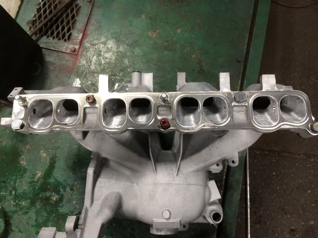
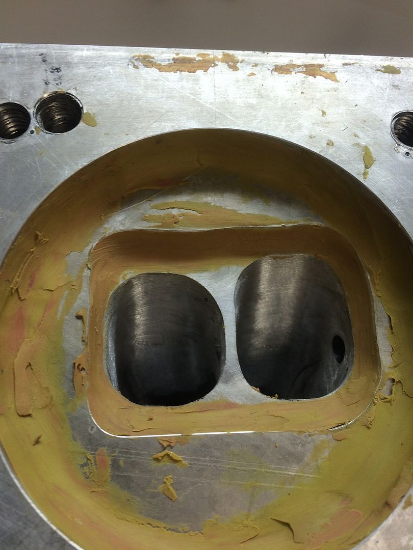
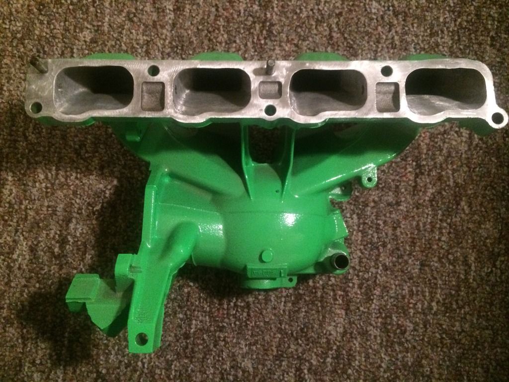
Next up was a gasket matched port and polished manifold. VTCS was removed but the holes were not sealed between runners. The same sealing methods were employed as before.
Manifold ports:
Sealed:
Here are the results:

The last stock variation of a stock manifold was a single runner manifold. Essentially a gasket matched manifold with a bit of throat porting and the runner divider removed. The same sealing methods were employed as previously.
Manifold ports:
Here are the results:

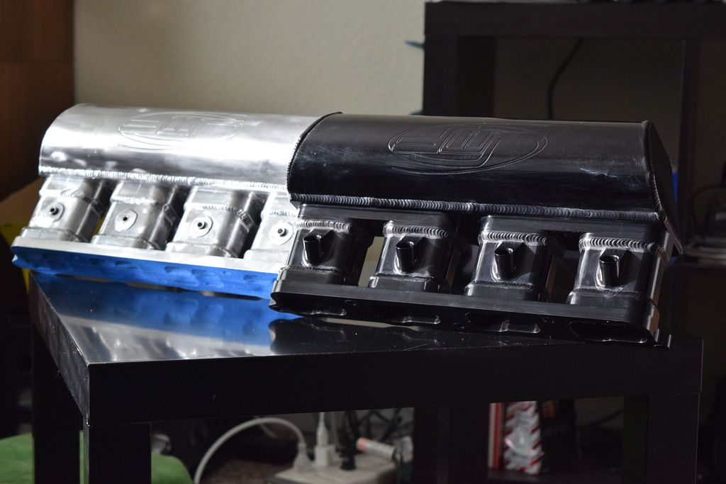
@Maisonvi; was generous enough to lend me two JMF manifolds. One is a single runner set up for Pi and the other is a split runner set up for meth. I was able to get the single runner manifold tested but not the split runner because I ran out of time but I will test the split runner when I return from my break next week. All of the PI bungs were taped off as well as the holes for the vacuum lines so all air would be drawn through the throttle body opening. The same sealing methods were used as the other tests.
Manifolds:
Here are the results:

So what are my thoughts on this? I discussed it with some of the IL Nator guys and I think that the reason for the flow imbalance between the runners on the stock manifold is because of the throttle body location. In order for air to go up the cyl 4 runner, it must make an almost 180* turn; that is something air does not like to do. On the other hand, to get to cyl 1 runner air has a mostly straight shot, not having to bend much. As to why 2 and 3 flow more than 1 and 4 I think is because of how the runners are connected to the plenum and the path they take is shorter than 1 and 4. Here's an illustration of what I mean:

As for why the JMF flows more on 1 and 4 I'm thinking it has something to do with this:


This flow imbalance was noted by SP63 on JMF's mani for the Focus ST. I believe that we are seeing the same thing on our manifold.
UPDATE: I've finished the testing for the JMF split runner mani by itself. Now that all the mani's I have have been tested by themselves I can finish testing with them connected to the head. The results for it are in the picture below. To my surprise the manifold flows ~15-20% less than the open runner manifold. I'm not really sure why the flow is so much less from this other than maybe it is causing turbulence in the port. Though I'm not really sure about that because the divider is CNC knife edged so it doesn't seem like it would really cause a lot of turbulence. Maybe the results with it connected to the head will tell a bit more.
Here is a more comparative view of the results. Please let me know what you guys think on this! If anyone has any non stock manifolds that I haven't tested yet and would like it tested please let me know!

EDIT (6/10/16): Here are the final results including the FoST mani with the DM spacer. As you can see, it flows EXTREMELY evenly. It's within 2% of all runners and flows 30-50% more than stock!

Before I get to my results I would just like to say, PLEASE do not compare my results to that of what others have posted. I have found little in the ways proper documentation for flow tested pieces and I really don't want this to turn into a, "well ______ said that their part flows xxx though". I don't care what a company has to say about their part, the point of this thread is to give an unbiased opinion, with properly documented results.
I'm going to start by covering some of the basics of the tests that pertain to all of the manifolds tested. The flow bench being used is a SuperFlow SF-600. This bench has a FlowCom computer attached to it which allows for great accuracy and ease of testing. All tests were done at a test pressure of 25" of H2O with a max variation of .3" H2O. The industry standard pressure for flow testing in the performance industry is 28" H2O. I chose to use 25" H2O because that is the pressure that the bench is calibrated for. I could have tested at 28" H2O but I decided I would rather have the most precise numbers I could get. The only real difference between 25" H2O and 28" H2O is that the test results would be a bit higher if the tests were done at 28" H2O. All results are in Cubic Feet per Minute (CFM).
To set a baseline I started with a totally stock intake manifold. The manifold was sealed with modeling clay to an adapter plate and sealed to the bench with clamps and a rubber gasket. I can't say for sure there weren't any leaks but if there were, it was less than a couple of CFM (aka mostly negligible). The VTCS was left intact and tests were done with the flappers open as well as closed. All ports not being tested were covered in tape so all air would be pulled through the throttle body opening. Lastly, every port was given a small exiting radius made of clay. This was done to help seal as well to keep variation of adapter plate placement a non factor.
Other ports sealed off:
The adapter plate sealed to the manifold:
Here are the results:
Next up was a gasket matched port and polished manifold. VTCS was removed but the holes were not sealed between runners. The same sealing methods were employed as before.
Manifold ports:
Sealed:
Here are the results:
The last stock variation of a stock manifold was a single runner manifold. Essentially a gasket matched manifold with a bit of throat porting and the runner divider removed. The same sealing methods were employed as previously.
Manifold ports:
Here are the results:
@Maisonvi; was generous enough to lend me two JMF manifolds. One is a single runner set up for Pi and the other is a split runner set up for meth. I was able to get the single runner manifold tested but not the split runner because I ran out of time but I will test the split runner when I return from my break next week. All of the PI bungs were taped off as well as the holes for the vacuum lines so all air would be drawn through the throttle body opening. The same sealing methods were used as the other tests.
Manifolds:
Here are the results:
So what are my thoughts on this? I discussed it with some of the IL Nator guys and I think that the reason for the flow imbalance between the runners on the stock manifold is because of the throttle body location. In order for air to go up the cyl 4 runner, it must make an almost 180* turn; that is something air does not like to do. On the other hand, to get to cyl 1 runner air has a mostly straight shot, not having to bend much. As to why 2 and 3 flow more than 1 and 4 I think is because of how the runners are connected to the plenum and the path they take is shorter than 1 and 4. Here's an illustration of what I mean:
As for why the JMF flows more on 1 and 4 I'm thinking it has something to do with this:
This flow imbalance was noted by SP63 on JMF's mani for the Focus ST. I believe that we are seeing the same thing on our manifold.
UPDATE: I've finished the testing for the JMF split runner mani by itself. Now that all the mani's I have have been tested by themselves I can finish testing with them connected to the head. The results for it are in the picture below. To my surprise the manifold flows ~15-20% less than the open runner manifold. I'm not really sure why the flow is so much less from this other than maybe it is causing turbulence in the port. Though I'm not really sure about that because the divider is CNC knife edged so it doesn't seem like it would really cause a lot of turbulence. Maybe the results with it connected to the head will tell a bit more.
Here is a more comparative view of the results. Please let me know what you guys think on this! If anyone has any non stock manifolds that I haven't tested yet and would like it tested please let me know!
EDIT (6/10/16): Here are the final results including the FoST mani with the DM spacer. As you can see, it flows EXTREMELY evenly. It's within 2% of all runners and flows 30-50% more than stock!
Last edited:
 Shooting to get it done the week after.